With a few last-minute improvements I've been able to substantially improve the performance of the printer. I slowed the stepper motor to reduce vibration, and I allowed a settling time after each motor movement before exposing the next layer of resin. I cleaned up the build platform, it is now a sheet of aluminum epoxied to the plywood. (And of course, within a couple of prints, it has gotten covered with a sheet of cured resin. Best laid plans...) I had been trying exposure times that were too short, so I went back to 60 seconds per layer.
If you'd like to see these prints and others, and the printer that made them, come to Maker Faire NYC this weekend at the New York Hall of Science in Queens, NY.
Here is a chess rook. It has an interior spiral staircase. The windows are a bit misshapen and the bottom flat surface is covered with a big glob of cured resin. I don't know why those things happened, but the detail on the parts that came out well isn't too bad.
This is a dodecahedron, one of the five Platonic solids. In the days of ancient Greece, this shape was the cause of some controversy because it could be used to prove the existence of irrational numbers, which ticked off Pythagoras something fierce. This was posted on Thingiverse, as was the rook.
Tomorrow I start a new job with Formlabs, a 3D printer company, and I'm psyched about that. Unfortunately, however, one of the conditions of my employment there is that I cease development on my own 3D printer. I spoke with their attorney and it all makes sense, it's the right thing to do, because my printer is entirely open source and they are selling a proprietary product. If I were to continue developing my printer, it would be too easy to unintentionally include pieces of their technology. So tonight I am putting the finishing touches on the Github repository.
Today was the first time I made a successful print with this printer design. I had hoped to print four dodecahedra at once. But I had some crud on the surface of my build plate, and I hadn't stirred the resin before printing, so only one of the four came out really well. Another was misshapen, and two of them never came together at all.
Here are the two that were at least coherent solids. I think with a little more learning and practice, I'll get to where I can make four that all look as good as the one on the right.
Here is the setup I'm using. If you've followed this blog, you'll recognize the stuff on the bucket. The box-like thing overhead was quickly cobbled together when I realized that my mirror wasn't reflecting enough UV light to make the resin cure properly, because the mirror's glass isn't transparent enough in the UV range. To remove the mirror from the optical path, I needed to put the projector directly over the bucket, pointing down.
Here is the best video I've found for working on bicycle chain. I haven't looked extensively but this one gave me the information I needed, starting at the 34-second mark. I had to buy a length of chain and one of these tools shown in the video. I thought I might need a thing called a "master link" but that's really unnecessary. Bicycle chain is one example of roller chain, a mechanical engineering term for chains that follow the same principle.
The chain I'm using is 1/2"-1/8" single speed chain, also known as #410 chain. The first number (1/2") is the pitch, the distance between the centers of two consecutive rollers. The second number is the width, the distance between inner plates. These numbers, together with the roller diameter, determine the shape of the sprocket teeth. For #410 chain the maximum roller diameter is 5/16".
If you're going to build a gadget using bicycle chain as a drive chain, remember that you'll need a tensioner somewhere, something you can adjust to take up slack in the length of the chain. You'll need at least an inch of adjustment available (twice the pitch). In my design, I made the stepper motor moveable to take up chain slack.
On to the topic of sprocket design. The approach I used is basically guided by the red curves in the diagram to the left. Some sprocket designs truncate the teeth, which reduces friction but engages each roller for a little less time. I probably should have done that but it's not really necessary. The OpenSCAD code for my sprocket design appears at the top of the sprockets.scad source file in the Github repository for my printer. I tested the sprocket (Thingiverse, Shapeways) to make sure that in the absence of unreasonable friction, the chain could freely engage and disengage the teeth as it moved around at fairly high speed (much faster than it will move on the printer most of the time) and that worked fine.
There are a few different pieces, so let me step through it. The outer thing is a difference operation, which means that the first part (the union) establishes a block of stuff and the other parts are removed from it. So we begin with a rectangular solid stretching in the X direction from one roller to the next, with a Z height equal to the width of the chain. To that we add the "tooth" part, defined by the two upper red curves in the previous diagram. The first two pieces we remove are the cylindrical cutouts in which the rollers will sit when closest to the sprocket's center, defined by the two lower red curves. Finally, a couple of flat surfaces are cut out to taper the tooth in the Z direction, which allows the sprocket to still engage nicely when the chain isn't precisely coplanar.
I found with the design above that those teeth can easily get stuck if one of the links in the bike chain is stiff. I haven't done a lot of bike chain work, and I would imagine that people who do probably get better at avoiding or fixing stiff links, but I'm not there yet. So one thing I did was to make much less "aggressive" sprocket teeth. For my application, I get away with much shallower teeth, and have updated both the Thingiverse design and the Shapeways store accordingly.
I might have neglected to mention this elsewhere (though I think it's mentioned in both those places) that the sprocket for the stepper axle takes a 1/4-inch long 4-40 machine screw as a set screw.
My too-clever-by-half use of laser-cut plywood gears ended badly. Small errors repeatedly accumulated to make the gears fit unreliably. It was a mess. I needed another idea.
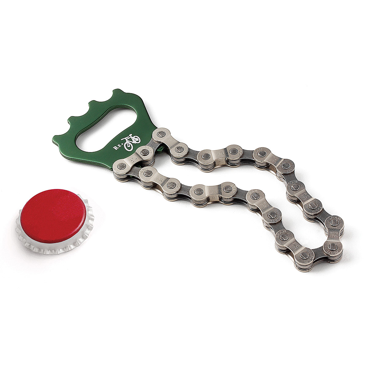
I started thinking about timing belts, especially something clever that Vik Olliver did on Rep Rap involving those ball chains used to switch ceiling lights on and off. I didn't really trust myself to be able to solder the ball chain together, and I continued scratching my head. Then I saw one of those bicycle chain bottle openers at a party, and realized that bicycle chain was the solution to my problem.
I started learning about roller chain and sprockets. It turns out sprocket tooth design is really pretty simple, much simpler than involute gear teeth, and I was able to design some sprockets with just a little study. It took a redesign because the first time, my stepper sprocket design assumed a friction fit would work, but when the part arrived, I discovered I'd need a set screw. In the picture to the left, I retrofitted a set screw on the initial sprocket design with sub-optimal results. This is probably adequate on a temporary basis, but an improved design is pending and should arrive by the end of August and should be in place for exhibition at Maker Faire.
So this is the new design. I think it retains the Steampunk flavor of the original design, if perhaps not quite as pronounced. It's a bit simpler and all the plywood cutting can be done by hand with a compass and a jigsaw. So my design goal that it should be buildable by a person of minimal craftsmanship (like myself) is intact.
Barring some disaster, I expect to be exhibiting this printer (hopefully in operation) at Maker Faire NYC 2014, at the New York Hall of Science in Queens, on September 20th and 21st. If you're reading this, you're invited to come see it. If you can't make it, I'll try to post as much information here, on Github, and on Youtube as possible.
The stereolithographic printer described in my last post works, but it has a lot of room for improvement. Two obvious improvements are to use a stepper motor to raise and lower the build platform, allowing for automated operation, and to accept standard input files such as the STL file format.
In this post, I'd like to look at improvements in the overall mechanical design, specifically intended to make this printer easy for other people to build. I envision this as a printer that could be easily and affordably built by an after-school club, at a price of less than $600. The projector I used cost me $350 and I'll assume that's the same price for others. Likewise I expect others would pay about $75 for a couple of bottles of UV-cured resin. That leaves $75 for everything else. You have a stepper motor, a stepper control board, and a Raspberry Pi. I have a little wiggle room left for laser-cut plywood, and a 5-gallon bucket from Home Depot. I get my laser-cutting done at danger!awesome in Cambridge, MA. The bucket is bright orange, and that's the color I've used in this design, where the plywood is yellow and green (the green pieces having gear teeth that mesh). The pale blue stick-things are 1/4-20 threaded rods, cheaply available at Home Depot. The brighter blue thing is the stepper motor. The three green gears surrounding the threaded rods have captive nuts, allowing the stepper to raise and lower the threaded rods in lock-step. I'm kind of pleased with this design and I think this is what I'd like to show at Maker Faire NYC this year.
Looking down into the bucket, we can see one more circular piece of plywood which is the build platform. When we raise the three threaded rods high enough, the build platform comes up out of the bucket, which holds a layer of resin floating atop a salt water bath (a trick I borrowed from the Peachy Printer). And in fact, you could use this setup with a Peachy Printer rather than a projector, and you'd save money by doing so.
These gorgeous pictures are courtesy of Tinkercad.com. It's a pretty wonderful thing if you're doing 3D design. One last picture, showing the projector bouncing light off the mirror to illuminate the resin.
I've been interested in hobbyist 3D printers for quite a while. A friend of mine, Jeff Keegan has an exquisite blog about his several-year hobby of building RepRap-style printers. He has donated a printer to the Boston Museum of Science. I took a stab at starting a RepRap-style printer years ago, but my level of dedication was not equal to the task.
A RepRap-style printer (technically, a fused-deposition-modeling printer) works by squeezing molten plastic out of a hot nozzle onto the workpiece, where the plastic cools, forming the next vertical layer. One FDM printer can create some of the parts for another FDM printer, or to replace its own parts when they get worn. This was the idea behind the RepRap project, that partially self-reproducing printers could be very cheap.
Stereolithograhic 3D printers operate on a different principle, using ultraviolet light to cure resin. The video above illustrates this process.
The past few weeks I have been spending way too much time trying to figure out how to build a stereolithographic printer of my own. I looked at a lot of things other people have done and started doodling some ideas. A few times I made or purchased parts for a particular approach and later realized that it wouldn't work for some reason. But after a lot of tinkering, I finally produced the octahedron on the right.
My printer is pretty crude and is due for a lot of improvements in the days ahead. I had ordered a stepper motor controller board that didn't work, so I needed to manually rotate the threaded rod that lowers the workpiece into the resin bath.
Hopefully this picture isn't too confusing. A lot of this is stuff from the hardware store: a bucket, a lot of plywood, nuts and bolts, a piece of aluminum screen, a threaded rod, two straight rods. That black shape at the top held in place with a bungee cord is a pretty standard conference-room projector. When the thing is printing, the projector aims down into the bucket, which holds a quantity of resin floating on a much larger quantity of salt water. The ultraviolet light from the pattern projected onto the resin cures it in a particular shape, forming one layer of the product, and then the threaded rot rotates, moving the product down by one layer-height.
Currently I'm using a layer-height of 1/40th of an inch, which turns out to be quite visible to the naked eye, so I want to go down to something more like 1/100th of an inch.
I plan to post plans and software on Github and Instructables to enable anybody to build one of these printers for just a few hundred dollars. Most of the cost ($350) is the projector. I'd like to do the RepRap thing of using lots of pieces made by an identical printer, which would involve some redesign.
My last post was really written primarily as background for this post. TL;DR: there is a lot we're doing right nowadays as software engineers, that we were screwing up badly 20 to 30 years ago.
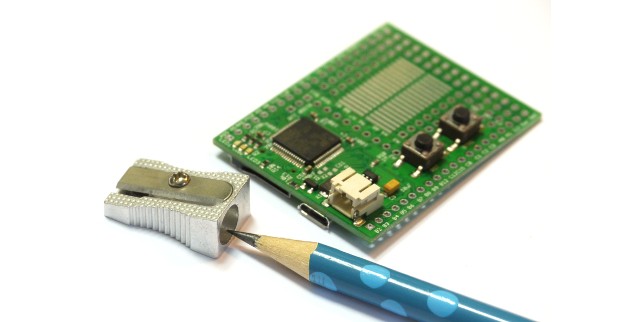
I am moved to write this post because I've been playing with the Espruino board (having pre-ordered one during the Kickstarter campaign), which runs JavaScript close to the metal on an ARM processor.
JavaScript is a cool language because it draws upon a lot of the experience that engineers have gained over decades. Concurrent programming is hard, so JavaScript has a bullet-proof concurrency model. Every function runs undisturbed to completion, and communication is done by shared-nothingmessage passing. In the browser, JavaScript gracefully handles external events with unpredictable timing. That skill set is exactly what is required for embedded hardware control.
Crockford once referred to JavaScript as "Scheme with C syntax". JavaScript has many of the features that distinguish Lisp and its derivatives, and which set apart Lisp as probably the most forward-looking language ever designed.
This video is Gordon Williams, the creator of the Espruino board, speaking at a NodeJS conference in the UK. One of the great things he did was to write code that can run on several different boards. I'm particularly interested in installing it on the STM32F4 Discovery board because it costs very little and looks pretty powerful as ARM microcontrollers go. There is a Youtube playlist that includes these videos and others relating to the Espruino board.
I got my bachelors degree in EE in 1981 and went to work doing board-level design. Most circuit assembly was wire-wrap back then, and we had TTL and CMOS and 8-bitmicrocontrollers. Most of the part numbers I remember from my early career are still available at places like Digikey. The job of programming the microcontroller or microprocessor on a board frequently fell to the hardware designer. In some ways it was a wonderful time to be an engineer. Systems were trivially simple by modern standards, but they were mysterious to most people so you felt like a genius to be involved with them at all.
After about 15 years of hardware engineering with bits of software development on an as-needed basis, I moved into software engineering. The change was challenging but I intuited that the years to come would see huge innovation in software engineering, and I wanted to be there to see it.
Around that time, the web was a pretty recent phenomenon. People were learning to write static HTML pages and CGI scripts in Perl. One of my big hobby projects around that time was a Java applet. Some people talked about CGI scripts that talked to databases. When you wanted to search the web, you used Alta Vista. At one point I purchased a thick book of the websites known to exist at the time, I kid you not. Since many websites were run by individuals as hobbies, the typical lifespan of any given website was short.
Software development in the 80s and 90s was pretty hit-or-miss. Development schedules were almost completely unpredictable. Bugs were hard to diagnose. The worst bugs were the intermittent ones, things that usually worked but still failed often enough to be unacceptable. Reproducing bugs was tedious, and more than once I remember setting up logging systems to collect data about a failure that occurred during an overnight run. Some of the most annoying bugs involved race conditions and other concurrency issues.
Things are very different now. I've been fortunate to see an insane amount of improvement. These improvements are not accidents or mysteries. They are the results of hard work by thousands of engineers over many years. With several years of hindsight, I can detail with some confidence what we're doing right today that we did wrong in the past.
One simple thing is that we have an enormous body of open source code to draw upon, kernels and web servers and compilers and languages and applications for all kinds of tasks. These can be studied by students everywhere, and anybody can review and improve the code, and with rare exceptions they can be freely used by businesses. Vast new areas of territory open up every few years and are turned to profitable development.
In terms of concurrent programming, we've accumulated a huge amount of wisdom and experience. We know now what patterns work and what patterns fail, and when I forget, I can do a search on Stackoverflow or Google to remind myself. And we now embed that experience into the design of our languages, for instance, message queues as inter-thread communication in JavaScript.
Testing and QA is an area of huge progress over the last 20 years. Ad hoc random manual tests, usually written as an afterthought by the developer, were the norm when I began my career, and many managers frowned upon "excessive" testing that we would now consider barely adequate. Now we have solid widespread expertise about how to write and manage bug reports and organize workflows to resolve them. We have test-driven development and test automation and unit testing and continuous integration. If I check in bad code today, I break the build, suffer a bit of public humiliation, and fix it quickly so my co-workers can get on with their work.
I miss the simplicity of the past, and the feeling of membership in a priesthood, but it's still better to work in a field that can have a real positive impact on human life. In today's work environment that impact is enormously more feasible.
Lots of times, these reports are much more about theoretical possibilities than real events. The nature of this vulnerability is that attackers can get peeks at blocks of memory in servers. That memory is changing all the time as the server is doing stuff. It's a possibility that the block of memory happens to have a copy of your password or other information when the attacker grabs it. Criminals who do these kinds of attacks will act on anything they find very quickly, because they know that victims will respond quickly by changing passwords, shutting off credit cards, etc. They would leave evidence if it had happened in any significant numbers, and there are places you could reliably find that evidence discussed (Bruce Schneier's blog, the EFF website) and the only mention is that certain big government agencies probably exploited the vulnerability, but it appears criminals probably haven't done so. The vulnerability existed for two years before it was publicly announced. So the NSA has your passwords, but they probably had them anyway. The big question is, what information do you feel you MUST protect? Financials: online banking stuff, or credit card stuff, or your Paypal account, or the online access to your IRA or H&R Block. Medical: your doctor's patient portal website, any logins you have with hospitals or medical centers. Dating websites? Sexual fetish websites? I think I've exhausted the limits of my paltry imagination. Those would be good passwords to change. You probably don't need to change your Facebook password, unless you're worried that NSA employees will get drunk and trash your Farmville farm. More information at http://heartbleed.com/ but it tends to run to the rather technical. You can test any website's vulnerability using the tool at http://filippo.io/Heartbleed/. Heartbleed is a buffer exploit, illustrated at http://xkcd.com/1354/. You tell the server you want some information which should be X letters long, but you ask for a much larger X, so that you get extra information from the server memory following what you asked for. The extra information might contain passwords and other profitable secrets. Buffer exploits have been understood for years. What is supposed to happen is that the server's software should reject the too-large X value, but this stuff is programmed by fallible humans. Here is a very good (but pretty technical) explanation of the programming mistake.
 Here is a chess rook. It has an interior spiral staircase. The windows are a bit misshapen and the bottom flat surface is covered with a big glob of cured resin. I don't know why those things happened, but the detail on the parts that came out well isn't too bad.
 This is a dodecahedron, one of the five Platonic solids. In the days of ancient Greece, this shape was the cause of some controversy because it could be used to prove the existence of irrational numbers, which ticked off Pythagoras something fierce. This was posted on Thingiverse, as was the rook.