Showing posts with label electronics. Show all posts

Saturday, January 09, 2016

Graceful shutdown for the Raspberry Pi

The Raspberry Pi is a great little board, but because it runs Linux, you risk corrupting the file system on the SD card if you simply switch off the power. The standard advice is to type "sudo shutdown -h now" and wait until the shutdown process has finished, or has at least unmounted all the file systems, before switching off the power.

What if the RPi is part of some embedded widget with no keyboard and screen? How then to initiate a shutdown, and how to know when it's finished? It was while contemplating the creation of just such an embedded widget that I hit upon this piece of brilliance. First, build this circuit.


How does this work? When you plug in the wall wart, we don't want to draw power from the 9 volt battery yet, so we want Q1 to be off. This is accomplished by using Q4 to keep the Q2/Q3 Darlington turned off. The wall wart power flows thru the three diodes in parallel and operates the switching voltage regulator (I picked up a bunch of these from some Chinese outfit on eBay). Meanwhile C1 charges to around 9 volts.

What happens when you yank the wall wart? Why, magic of course. Magic happens. Specifically, Q4 turns off, and C1 begins to discharge thru R1 and R6, turning on the Darlington pair, which turns on Q1 so that now the switching regulator is running on battery power. The battery power remains on for some multiple of the RC time constant (100 uF * 500K = 50 secs), and you end up with about two minutes to get the Raspberry Pi to shutdown.

I've started a Github repository for this, and it includes the two scripts that make graceful shutdown a service that starts automatically when the RPi boots.

Sunday, November 15, 2015

How does the Tooba's keyboard work?

The question I was most frequently asked when exhibiting the Tooba was about how the keyboard works. I was asked this by people who were obviously intelligent, and I have a deep understanding of it myself, so you would think there would be no problem in communicating it.

The short answer is, when you touch the copper contact, its effective capacitance increases, causing a change in an RC time constant which can be quickly measured with very simple electronics. The problem is that nearly zero otherwise intelligent people in our society understand capacitance.

I tried several different ways to explain this to people. Usually I said, "it works the same way as the touch screen on your phone", and that's true but it doesn't explain anything. It only gives people a known reference point to indicate that it's not physically impossible.


Capacitance is actually a pretty straightforward idea. You have two parallel metal plates. A battery or some other force pulls electrons out of one plate and pushes them into the other, so the first plate becomes positively charged and the second plate becomes negatively charged.

Opposite charges attract, so there is a force pulling the plates together, but they are mechanically held apart, usually by a layer of insulating material. The attractive force therefore acts upon the charges themselves, the excess electrons in the negative plate and the "holes" where electrons are missing in the positive plate. The negative and positive charges want to stay where they are, a bit like inertia, and this manifests as a measurable voltage difference between the plates. The only way to change that inertia is a current, a flow of electrons, into one plate and out of the other. A flow of 6.24x10¹⁸ electrons per second (or one coulomb per second) is one ampere.

Capacitors can be big or small. Capacitance is the size C measured in farads. Great, what the hell does that mean? Remember that the inertia of charge is measurable as a voltage V. The amount of charge is Q, the number of coulombs originally pumped into the plates by the battery. Then the magic formula is Q = C x V, or V = Q / C. How this pertains to the Tooba is that if Q is the same and C gets bigger, then V gets smaller.

Here is the touch-sensor circuit in the Tooba. The input on the left and the output on the right are I/O pins of the microcontroller. The left one is an output that drives electrons into and out of the capacitor, and the right one is an input to measure the voltage on the capacitor. It's a crude measurement, just a comparison to a threshold voltage that gives a zero or one.

BRIEF DIVERSION: In electronics, current is actually the direction opposite to how electrons are moving. This backwards convention is (no kidding) because Benjamin Franklin didn't have know whether the carriers of charge were positive or negative; the observable behavior was the same to him. He guessed, with a fifty-fifty chance of getting it right, and got it wrong. His mistake got codified into all of electronics, forever and ever, amen.

The output on the left is set to logical zero for a little while. The diode quickly discharges the capacitor to the same low output voltage representing a logical zero. Then the output is set to logical one, a higher voltage. The current flows to the right, against the direction of the one-way diode, so all the current flows through the resistor which slows down the movement of electrons. Here's the tricky part: if the capacitor is small, the voltage rises quickly, and if the capacitor is large, the voltage rises slowly. After a certain fixed amount of time, the voltage will just cross the zero-one threshold if your finger was not touching the copper, and the input will read a one. But if you touched the copper, the voltage will rise too slowly and the input will read a zero.

There is one more tricky bit to this. You may have been told in school that you always need to complete a circuit. Pushing current into the top of the capacitor would require that the bottom of the capacitor is connected to the ground in the Tooba. It turns out that capacitors are the one exception to this "complete the circuit" rule. You can (briefly) push current into a single plate and it will behave like a capacitor even without a second plate. That's why you can play the Tooba (or use the touch screen of your phone) without having a wire attached to you to complete the circuit.

Addendum - a friend read this post and wrote:
There's a missing piece in your explanation of capacitance: yes, the negative and positive charges do attract one another, but the charges in each plate also more strongly repel the same-sign charges in that same plate. That creates a restoring force that tries to push current back through the circuit to discharge the capacitor. 
The greater the capacitance, the smaller this net restoring force is. (You can think of a capacitor of higher capacitance as giving more room for the charges to spread out so they're not so crowded, or putting the plates closer together so that the "inertial" attraction across the gap is greater, or both.) 
If you touch one plate, a teeny bit of the charge can flow into your finger, or charges can become polarized in your finger so that some of the electric restoring force is cancelled out. Either way, it increases the capacitance by relieving some of the electric back-pressure through the circuit. And that's why you don't have to complete a circuit yourself.

Friday, July 24, 2015

The Tooba

Way back when, one of my friends in high school was a guy named Dave Wilson whose father got him into Moog-style analog electronic music synthesizers. Dave created a museum of historical synthesizers in his home in Nashua, New Hampshire. Through my high school and college years, we exchanged ideas and circuits and bits of lore for various synthesizer hacks. These synthesizer modules were implementing mathematical functions that could be implemented in digital electronics. So we both at various points and in various contexts wrote code to do that.

The Tooba is going to be some of that built into a short length of 3" PVC tubing. There will be a two or three-octave touch sensitive keyboard and some linear slide pots for various synth parameters. Sound will be generated in the same Teensy 3.1 controller board that scans the keyboard. Unless the poor little CPU gets overwhelmed, then maybe I'll put in a second Teensy for sound generation.

Here is a prototype, mostly testing the touch-sensitive keyboard. For this version the sound was generated by Timidity running on a Raspberry Pi, and the form factor is obviously different. The keyboard misbehaved in this video because of a sagging under-powered 12-volt supply.

UPDATE: Wrong! The keyboard misbehaved because of a programming error identified much later, now corrected.

I'll add more to this post as the thing gets closer to completion.

I had some confusion about the date for the Rhode Island Mini Maker Faire (last year it was a month after the NYC Maker Faire) so I had to hustle when I got the date correct. But I managed to pull it off and have got the thing working.

I also had to figure out how to mount the copper hexagons on the PVC tubing. Eventually my technique got good enough, but by then I had a mix of well-soldered and poorly-soldered hexagons, and the latter periodically pop off. So in the video below you'll see some missing hexagons that I need to replace before I head down to Providence.

So that's the gadget. There is a lot of clean-up to do on the mechanical design. Now I feel it's stable enough to justify laying out a printed circuit board. And the inside wires should be replaced by ribbon cable. But hey, it's working.

Monday, March 02, 2015

An overview of the 2014 printer

People have been asking for an overview of the 3D printer that I showed at Makerfaire NYC 2014. I designed it myself, borrowing a couple of ideas from other printers. My printer builds objects from a liquid resin that solidifies under ultraviolet light. Your dentist may use similar stuff to fill cavities. I get the ultraviolet light from an unmodified conference room projector that cost me about $350, the single biggest expense of the whole project. The most important design principle was that a person of very low craftsmanship like myself should be able to build the thing. It pretty much does not require precision at any point in the construction. There is a Github repository for all this stuff, including a DIY slicer.

The idea to use a projector rather than steering a laser came from the B9 Creator printer. The Peachy printer gave me the idea of floating resin on salt water and projecting the light onto the surface of the liquid. The idea to raise and lower the build platform using three threaded rods driven by a bicycle chain was my own, and it turned out not to be such a great idea.

Soon I plan to post some of my plans for a 2015 printer. Right off the top of my head I can think of four worthwhile goals.

  • Bring it to both the Bay Area Makerfaire and the NYC Makerfaire.
  • Replace the bicycle chain and those three threaded rods with something simpler and more reliable. The obvious candidate is GT2 belts such as are sold by Adafruit.
  • Clean up the electronics and software so I don't need a laptop to control it.
  • Replace the orange bucket with something with transparent sides, like an aquarium tank, so that people can watch the printing process.


With the bicycle chain not yet in place, the printer looks like this. Those gray sprockets engage the bicycle chain, which goes around in a sort of diamond shape. The orange bucket is one of the three-dollar buckets from Home Depot. The plywood, nuts and bolts, and threaded rods also came from Home Depot. At this particular point in the work, I thought I would suspend a mirror over the top of the bucket at 45 degrees, which is why you see a piece of wood in the upper right of the photo. But I didn't know about first surface mirrors then, and I lost enough UV going through the glass twice that I couldn't get the resin to solidify, so I then positioned the projector directly over the bucket, pointing downward.

The sprockets were designed using OpenSCAD and initially the teeth were too pointy - correct in theory but too sticky for real-world bicycle chain, so you can see where I cut off the points, and later revised the design. If you order sprockets from my Shapeways store, they should now work fine.


Here is the printer fully assembled. The bicycle chain is driven by a stepper motor. Each revolution of the stepper motor (200 steps) raises or lowers the build platform by 1/20th of an inch because the thread on the threaded rods is 1/4-20.

When it's printing, it looks like this. Only where the light is the strongest is the resin solidified. The resin happily ignores ambient diffuse daylight in the room where I'm printing, so I don't need to use dark room lighting.

Pictured below are some of the objects I've printed with the thing. I started out with a bottle of green resin and when that started getting low, I added a bottle of clear, so my things tend to vary between green and clear.

Previous blog posts discussing this printer in its earlier stages

Tuesday, April 15, 2014

A few decades' progress in computers and electronics

I got my bachelors degree in EE in 1981 and went to work doing board-level design. Most circuit assembly was wire-wrap back then, and we had TTL and CMOS and 8-bit microcontrollers. Most of the part numbers I remember from my early career are still available at places like Digikey. The job of programming the microcontroller or microprocessor on a board frequently fell to the hardware designer. In some ways it was a wonderful time to be an engineer. Systems were trivially simple by modern standards, but they were mysterious to most people so you felt like a genius to be involved with them at all.

After about 15 years of hardware engineering with bits of software development on an as-needed basis, I moved into software engineering. The change was challenging but I intuited that the years to come would see huge innovation in software engineering, and I wanted to be there to see it.

Around that time, the web was a pretty recent phenomenon. People were learning to write static HTML pages and CGI scripts in Perl. One of my big hobby projects around that time was a Java applet. Some people talked about CGI scripts that talked to databases. When you wanted to search the web, you used Alta Vista. At one point I purchased a thick book of the websites known to exist at the time, I kid you not. Since many websites were run by individuals as hobbies, the typical lifespan of any given website was short.

Software development in the 80s and 90s was pretty hit-or-miss. Development schedules were almost completely unpredictable. Bugs were hard to diagnose. The worst bugs were the intermittent ones, things that usually worked but still failed often enough to be unacceptable. Reproducing bugs was tedious, and more than once I remember setting up logging systems to collect data about a failure that occurred during an overnight run. Some of the most annoying bugs involved race conditions and other concurrency issues.

Things are very different now. I've been fortunate to see an insane amount of improvement. These improvements are not accidents or mysteries. They are the results of hard work by thousands of engineers over many years. With several years of hindsight, I can detail with some confidence what we're doing right today that we did wrong in the past.

One simple thing is that we have an enormous body of open source code to draw upon, kernels and web servers and compilers and languages and applications for all kinds of tasks. These can be studied by students everywhere, and anybody can review and improve the code, and with rare exceptions they can be freely used by businesses. Vast new areas of territory open up every few years and are turned to profitable development.

In terms of concurrent programming, we've accumulated a huge amount of wisdom and experience. We know now what patterns work and what patterns fail, and when I forget, I can do a search on Stackoverflow or Google to remind myself. And we now embed that experience into the design of our languages, for instance, message queues as inter-thread communication in JavaScript.

Testing and QA is an area of huge progress over the last 20 years. Ad hoc random manual tests, usually written as an afterthought by the developer, were the norm when I began my career, and many managers frowned upon "excessive" testing that we would now consider barely adequate. Now we have solid widespread expertise about how to write and manage bug reports and organize workflows to resolve them. We have test-driven development and test automation and unit testing and continuous integration. If I check in bad code today, I break the build, suffer a bit of public humiliation, and fix it quickly so my co-workers can get on with their work.

I miss the simplicity of the past, and the feeling of membership in a priesthood, but it's still better to work in a field that can have a real positive impact on human life. In today's work environment that impact is enormously more feasible.

Thursday, May 30, 2013

Still plugging away on the FPGA synthesizer

I really bit off a good deal more than I could chew by trying to get that thing running as quickly as I did. A lot of what I'm doing now is going back over minute assumptions about what should work in real hardware, trying to get MyHDL's simulator to agree with Xilinx's ISE simulator (ISE Sim doesn't like datapaths wider than 32 bits) and trying to get the chip to agree with either of them. The chip seems to have a mind of its own. Very annoying.

Anyway I've moved this stuff into its own Github repository so you can show it to your friends and all stand around mocking it without the distraction of other software I've written over the years. So, for as long as it still doesn't work (and with, I hope, the good grace to do it behind my back), y'all can continue with that mocking. Once it actually does what it's supposed to do, all mocking must of course cease.

Saturday, May 18, 2013

My FPGA design skills are a little rustier than I thought

Today I'm going to Makerfaire in the Bay Area. I'd had an idea percolating in my head to use an FPGA to implement fixed-point equivalents of the analog music synthesizer modules of the 1970s, and gave myself a couple of weeks to design and build a simple synthesizer. I'd been a synthesizer enthusiast in high school and college, having attended high school with the late David Hillel Wilson and had many interesting discussions with him about circuit design for synthesizers, a passion he shared with his father. While he taught me what he knew about synthesizers, I taught him what I knew about electronics, and we both benefitted.

Now I have to confess that since my switch to software engineering in the mid-90s, I haven't really done that much with FPGAs, but I've fooled around a couple of times with Xilinx's ISE WebPack software and stumbled across 
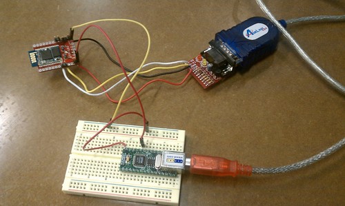
MyHDL, which dovetailed nicely with my long-standing interest in Python. So I ordered a Papilio board and started coding up Python which would be translated into Verilog. My humble efforts appear on Github.
There was a lot of furious activity over the two weeks before Makerfaire, which I hoped would produce something of interest, and I learned some new things, like about delta-sigma DACs. Being an impatient reader, I designed the delta-sigma DAC myself from scratch, and ended up diverging from how it's usually done. My design maintains a register with an estimate of the capacitor voltage on the RC lowpass driven by the output bit, and updates that register (requiring a multiplier because of the exp(-dt/RC) term) as it supplies bits. It works, but has a failure mode of generating small audible high frequency artifacts particularly when the output voltage is close to minimum or maximum. On the long boring flight out, I had plenty of time to think about that failure mode, and it seems to me the classic delta-sigma design would almost certainly suffer from it too. I think it could be reduced by injecting noise, breaking up the repetitive patterns that appear in the bitstream.

I like Python a lot but I'm not sure I'm going to stay with the MyHDL approach. As I learn a little more about Verilog, it seems like a probably better idea to design directly in Verilog. The language doesn't look that difficult, as I study MyHDL's output, and while books on Verilog tend toward expensive, some of them are more affordable. Those books are on the Kindle, and a couple others are affordable in paper form.

MyHDL-translated designs do not implement Verilog modularity well, and I think it would be good to build up a library of Verilog modules in which I have high confidence. MyHDL's simulation doesn't always completely agree with what the Xilinx chip will do. And while MyHDL.org talks a lot about how great it is to write tests in Python, the Verilog language also provides substantial support for testing. Verilog supports signed integers, but as far I've seen, MyHDL doesn't (this is INCORRECT, please see addendum below), and for the fixed-point math in the synth modules, that alone would have steered me toward straight Verilog a lot sooner had I been aware of it.

It appears the world of Verilog is much bigger and much more interesting than I'd originally thought. I've started to take a look at GPL Cver, a Verilog interpreter that (I think) has debugger-like functions of setting breakpoints and single-stepping your design. I had been thinking about what features I'd put into a Verilog interpreter if I were writing one, and a little googling showed me that such a thing already existed. So I look forward to tinkering with CVer when I get home from Makerfaire.

EDIT: Many thanks to Jan Decaluwe, the developer of MyHDL, for taking the time to personally respond to the challenges I encountered with it. Having had a couple of days to relax after the hustle and bustle of Makerfaire, and get over the disappointment of not getting my little gadget working in time, I can see that I was working in haste and neglected to give MyHDL the full credit it deserves. At the very least it explores territory that is largely uncharted, bringing modern software engineering to the HDL world where (like all those computational chemists still running Fortran code) things have tended to lag behind the times a bit.

In my haste, I neglected the documentation specifically addressing signed arithmetic in MyHDL. I didn't take the time to read the docs carefully. As Jan points out in his writings and in the comment to this blog, MyHDL's approach to signed arithmetic is in fact simpler and more consistent than that of Verilog. What does signed arithmetic look like in MyHDL? It looks like this.

    # INCORRECT
    >>> x = Signal(intbv(0)[8:])
    >>> x.next = -1
    Traceback (most recent call last):
        ...blah blah blah...
    ValueError: intbv value -1 < minimum 0

    # CORRECT, range is from min to max-1 inclusive
    >>> x = Signal(intbv(0, min=-128, max=128))
    >>> x.next = -1      # happy as a clam

In the case where MyHDL's behavior appeared to diverge from that of the physical FPGA, my numerically-controlled amplifier circuit above uses one of the hardware multipliers in the XC3S500E, which multiplies two 18-bit unsigned numbers to produce a 36-bit unsigned product. When my music synthesizer was at one point unable to make any sound, I tracked it down to the amplifier circuit, which was working fine in simulation. There was already a hardware multiplier working in the delta-sigma DAC. I poked at things with a scope probe, and scratched my head and studied my code and studied other peoples' code and ultimately determined that I needed to latch the factors in registers just prior to the multiplier. Whether it's exactly that, I still can't say, but finally the amp circuit worked correctly.

I wrongly concluded that it indicated some fault in MyHDL's veracity as a simulator. If it didn't work in the chip, it shouldn't have worked in simulation. But with more careful thought I can see that it's really an idiosyncrasy of the FPGA itself, or perhaps the ISE Webpack software. I would expect to run into the same issue if I'd been writing in Verilog. I might have seen it coming if I'd done post-layout simulation in Webpack, and I should probably look at doing that. Once the bits are actually inside the chip, you can only see the ones that appear on I/O pins.

Monday, March 04, 2013

The Digi-Comp 1 rides again?

As computer people go, I'm rather an old fart, and my favorite childhood toy was this plastic computer, the Digi-Comp 1. See the three horizontal red things that run almost the full width? Those are flipflops, and the window on the left shows whether they are in the zero or one position. The six vertical metal bars in front are AND gates, and the little white tubes stuck onto the pegs on the fronts of the flipflops tell whether that bit is factored into the AND term. The six red plastic things on the top, together with similar stuff on the back, form three OR gates, which drive the values of the flipflops on the next clock edge. The two white sliders on the bottom worked in opposition, providing a hand-powered two-phase clock to drive all this stuff.

Over the past couple of days I placed an order with danger!awesome, a laser cutter shop in Cambridge MA. They have a nifty collection of laser cutters and were happy to hear that design files are available on the Thingiverse website. So I ordered some stuff and picked it up this evening, and that was fun. I had hoped they could make me this marble binary adder, but the designer didn't supply design files they could use. So no marble adding machine for me. Darn.
Thinking about that, my mind inevitably went back to the Digi-Comp 1. I started wondering whether I could build a Digi-Comp 1 using laser cut plywood, like the other trinkets I picked up this evening (a Companion Cube, a desktop trebuchet, a Shrimpbot, and a few little animals). Could that be feasible? The Digi-Comp 1 was basically a programmable logic array, which consists of two rectangular regions, one for AND gates and one for OR gates. On the Digi-Comp 1 these are respectively the front surface and the back surface of the device.

I thought about this for a while and came up with some very incomplete rough sketches to solve the problems of how the gates would work and how the binary values should be latched for one clock cycle. As with the Digi-Comp 1, this would be a rectangular thing with the AND plane on the front and the OR plane on the back. The flipflops would be horizontal bars along the front with two positions (left=0, right=1) and possibly the same window display that appears on the original Digi-Comp 1. The AND gates are vertical bars also on the front, connecting to vertical bars on the back. The OR bars on the back can move left and right if permitted. At a certain point in the clock cycle, the horizontal position of each OR bar is inverted with a little lever and latched as the new position for the corresponding flipflop. There is still a lot of mechanical engineering to think about. Should the bars be retracted with springs or rubber bands? There needs to be a lot of machinery to get everything to move when and where it's supposed to, and there needs to be a crank on the side to drive it. So there will be cams and gears and all sorts of fun stuff.

UPDATE: I found a place called Minds-On Toys that is selling a Digi-Comp kit which reproduces the exact mechanical design of the original. Looks very nice, except for the labor-intensive-looking bit at the bottom about fabricating your own plastic tubes.

Friday, October 05, 2012

Blogging from a Raspberry Pi board

I've plugged an Ethernet cable into the Raspberry Pi and brought up the Midori web browser (which I had previously never heard of). As a web-browsing experience, the RPi is extremely slow, but it works. Google's new authentication scheme is a little dubious about Midori, not too surprising. But it rendered Facebook readably and I was able to look at some of my pictures on Flickr.

I intend to find some interesting hardware hack for the board, probably a musical instrument of some sort. Of course it won't be running X Windows at that point. If I get ambitious I might try to figure out how to create a stripped-down X-less Raspian distribution. I've done a little bit of distro hacking on Ubuntu in the past.

Even without X, I'm concerned about performance issues. Linux is not normally used for real-time use, but apparently I'm not the first person to wonder if that's feasible. Well I think I've exhausted my patience here.

Back on a normal computer. That was interesting, but enough is enough. Any RPi hacking that reaches a state of readiness for public consumption will be posted on Github, and notifications will appear here.

Before I forget, one handy note to other Yanks thrown by Raspian's curious keyboard mapping. You might have skipped over most of the options in raspi-config as I did (the first thing that appears on your screen after all those boot messages finish). Look for "keyboard configuration" and look for the canonical U.S. keyboard choices.
Here's a custom search engine for Raspberry Pi stuff, courtesy of Google.

Friday, September 28, 2012

Fun with the Raspberry Pi

If you've heard about the Raspberry Pi, (wikipedia, elinux.org) a $35 single-board Linux computer, you probably won't learn much new here. The main point of this post is that I got mine to boot, so I do have one or two small bits of advice to pass on to those working toward that goal. First, photographic evidence (veracity: if I were faking it I wouldn't put a big reflected flash in the middle of the screen).

Here's the board booting. Booting (and everything else) is a little slower on the Raspberry Pi than you're probably accustomed to. But then, hey, it's $35, and you can stuff it into whatever piece of hardware you're building and have full-blown Linux with X Windows. So live with it.

My experience has been that at least in the near future, it's not really $35. Here's what happens: the Raspberry Pi folks build a bunch of boards and sell them for $35, but they get picked up by people who want to resell them, so you end up getting yours on eBay for somewhere in the $55 to $70 range. Eventually this mischief will end and the price will stabilize.

 Photographic evidence number two: the board has booted into X Windows. This is using the recommended-for-beginners Debian-based distribution, 2012-09-18-wheezy-raspbian.zip, which unpacks into 2012-09-18-wheezy-raspbian.img, and obviously the date in that name will be updated periodically.

So here are the tips for fellow beginners:
  • First, remember this board is designed for complete novices, and even, heaven help us, artists. Do not despair, you ARE smart enough to get it working.
  • The Raspberry Pi folks warn you away from micro-SD cards, but the one I'm using works fine.
  • You may find that your keyboard is mapped in a funny way. My (@) key and (") key were swapped, and the (#) key was mapped to a British pound sign (£). One solution to this appears here. Mine was to create the file /home/pi/.xsessionrc which contained this line:
setkbmap us -option grp:ctrl_shift_toggle

A better approach to the keyboard issue is one of the options in raspi-config (the first thing that appears on your screen after all those boot messages finish). Look for "keyboard configuration" and select the canonical U.S. keyboard choices.

Everything else seems to be working, but I haven't tried to do much yet. I have no idea how to talk to GPIOs or other peripherals yet, but I've done that with other Linux boards and expect that my past experience will get me there pretty painlessly. That, and there is a HUGE community for this thing.

Looking forward to checking out Adafruit's WebIDE when time permits. The development system runs as a web server on the board, and you develop in the browser on your laptop over a network connection.


And now for your viewing pleasure, assorted Raspberry Pi pr0n:
 

Thursday, September 27, 2012

Cool new 3D printers

I don't want to fall into the habit of only blogging once per year about MakerFaire. So this post is actually about a crop of cool new 3D printers, and I'll probably see a few of them there, but it's not about MakerFaire proper. These all fall in the $1500 to $2500 price range.


First up is Makerbot's Replicator 2. There is some controversy around this one, because it's a mix of open source technology under the GPL, and some new technology that's very likely not open source, which allows for a much higher print quality. The open source 3D printer advocates are concerned that it violates the GNU General Public License. The open source technology is primarily the work of Adrian Bowyer who started the RepRap project, and he's given (unenthusiastic) permission to Makerbot to use it.

One of the RepRap enthusiasts is my friend Jeff, who will have a table at MakerFaire this year to show off the printer that has occupied two or three years of his nights and weekends. I like Jeff and I think he'll probably not be too happy with Makerbot's decision to include closed-source technology. But the step up in quality for the price is pretty appealing for a non-GPL-purist like myself. I don't worry about running GPL software on closed-source laptops, after all.

Second is the FORM1 from some Media Lab folks. I don't know much about these folks or their history, but the Media Lab has been at the cutting edge of high-end 3D printing for a couple of decades now, so they've probably got something pretty interesting. I think their raw material is a liquid rather than the long plastic spaghetti sticks used by most other affordable machines (based on one photo on their Kickstarter page). This is the most expensive of the lot, price currently listing as $2500.

Third is the UP!Plus from 3D Printing Systems. Their output doesn't look as nice as the Replicator 2 or the FORM1, but they are at the more affordable end.


What's cool about all these printers and some other new ones is that the user friendliness and quality of output are improving rapidly in recent years. Before long, these things will be popping up in homes, dorm rooms, high schools, and the local mall.

Makerfaire NYC 2012 is this weekend, and I'll be there to checkout 3D printers, microcontroller boards, art installations, and whatever else is around, and I'll blog about what I see.

Monday, September 19, 2011

MakerFaire NYC 2011

I went to MakerFaire at the NY Hall of Science, Queens, NY on September 17th and 18th, and took plenty of photos. Like last year, the location was the site of the 1964 World's Fair. Even though I grew up pretty close to New York, I didn't get to see the World's Fair as a child, so I'm glad to have these opportunities to see what's left of it.
As was true last year, there were lots of 3D printers and CNC milling machines. My impression this year was that a much larger percentage of them were hobbyist efforts rather than high-end commercial projects. I think that's a good thing. There seems to me to be a maturing of the 3D printer hobbyist effort in general, and the gradual emergence of more small businesses like Bre Pettis's Makerbot. The hard technical challenges (the big one being getting the extruder nozzle to work just right) have pretty much been identified now.

As I looked at some of the products, which have been improving in resolution, it occurred to me that an interesting approach would be, instead of going with increasingly fine nozzles, to use a coarse nozzle to place a slightly oversized drop of plastic, let that drop cool and harden, and then bring in a milling tool to shape it. This would mean moving back and forth frequently between the extruder nozzle and the milling tool, so it would need some tinkering and might not end up being an improvement.

There were lots of other tools, things on display, and cool stuff to see. I was really impressed with an elegant (if low-res) volumetric display called Lumarca. Essentially the guy uses a projector to project colors onto lengths of monofilament fishing line in the viewing volume, and by carefully controlling the projected image, he individually controls what colors appear along each length of monofilament.

There were a few interesting vehicles, like motorized skateboards and a Segway clone. Those were fun.

One thing I found interesting was that in addition to the expected Arduino stuff (which has the full weight of O'Reilly Publishing behind it), there were a good number of boards with more advanced microcontrollers, particularly ARM Cortex-M3 controllers. This interests me because with their larger address spaces and fuller feature sets, ARM processors can run Linux OSes or Python interpreters or other big pieces of code  beyond the itty-bitty programs that will fit on an Arduino. Teho Labs had a nice line of Cortex M3 boards. They shared space with Dangerous Prototypes who were showing off their Web Platform board.

I did get pretty tired and sore walking around so much, and needed some Advil. But it was definitely worthwhile. Maybe I'll have some project next year so that I can have a booth of my own.http://www.arm.com/products/processors/cortex-m/cortex-m3.php

Sunday, September 11, 2011

We need to build more educational computers

When I was a kid, I had this absolutely wonderful educational computer called Digi-Comp. It was very simple, with only three bits of state, and that was fine for learning an awful lot of basic stuff about computers. And it was sturdy as anything. I must have disassembled and reassembled it hundreds of times and it never broke and never stopped working. Somebody needs to design a 21st century mechanical computer using an inexpensive service like Ponoko or Shapeways or 100kGarages or Big Blue Saw to do laser cutting or 3D printing.

When I was in college, I saved up money to buy a KIM-1 single-board computer with a 6502 microprocessor, a hexadecimal keypad, and six seven-segment digit displays. I learned a lot of what became my career playing with that thing, writing little assembly language programs, soldering TTL chips to it, and generally having a great time. When I left school, I bought an old ASR-33 teletype from the school's department for retiring obsolete junk, and used it to give the KIM-1 a 300 baud line printer. Back in those days we had extraordinarily low thresholds of entertainment. Still, it was educational.

We need to be building more of this kind of stuff today. The things we build need to be easily hackable and easy to form user communities around. I guess you could say we already have something like the KIM-1 with today's Arduino, but it never fills me with intrigue like the KIM-1 did, where you were literally typing in machine opcodes onto that hex keypad, and they're showing up in the LED digits. It gives you a real sense of intimacy with the entire process of computation. Compiling C code never gets you quite that close to the action.

If you regard the Digi-Comp and the KIM-1 as two points along a spectrum of sophistication, we probably ought to plan on a third more advanced point, given that the KIM-1 is about 30 years old now. I've been doing some puttering with ARM-7 and ARM-9 boards of various kinds, some so capable as to run Linux, and I think that's a good third point because that's the kind of hardware that appears in modern consumer devices.

Sunday, June 19, 2011

Thinking about going solar

I answered an ad by an outfit called One Block Off the Grid (1BOG) which organizes the installation of solar panels on people's roofs. When I say "organize", I mean not only that they take care of various complex logistical issues including lining up a NABCEP-certified installer, but also that they try to consolidate system purchases to bring costs down. Over the past couple of years this has become big business in the U.S. because of state and federal government incentives encouraging installation.

The 1BOG folks sent me a proposal with numbers in it, and I have 30 days to make a decision during which the proposed price is guaranteed. I also spoke briefly with SolarFlair, a similar outfit here in my town, that does the same sort of purchase consolidation and does the installation themselves. Since my 30 days is nearly expired, I'm hoping to drop into the SolarFlair office some time this week and talk numbers with them.

In my own state of Massachusetts, the situation is that people with solar panels produce SRECs (wikipedia, explanatory video) worth around $500 each time the solar panels produce a megawatt-hour.
Massachusetts' renewables portfolio standard (RPS) requires each regulated electricity supplier/provider serving retail customers in the state to include in the electricity it sells 15% qualifying renewables by December 31, 2020... Solar Renewable Energy Certificates (SRECs) represent the renewable attributes of solar generation, bundled in minimum denominations of one megawatt-hour (MWh) of production. Massachusetts' Solar Carve-Out provides a means for SRECs to be created and verified, and allows electric suppliers to buy these certificates in order to meet their solar RPS requirements. All electric suppliers must use SRECs to demonstrate compliance with the RPS. The price of SRECs is determined primarily by market availability, although the DOER has created a certain amount of market stability by establishing a state Solar Credit Clearinghouse Auction (where prices are fixed at $300/MWh), as well as the Solar Alternative Compliance Payment (SACP) for the state RPS (set at $550/MWh for 2011). The Solar Credit Clearinghouse will only be utilized if or when SREC generators cannot sell their SRECs on the open market; the fixed price of $300/MWh effectively acts as price floor. The SACP, on the other hand acts, acts as a ceiling on the value of SRECs because it is the per-MWh payment that electricity suppliers must make if they fail to obtain enough SRECs to cover their RPS obligation.
There is a federal tax credit of 30% on the cost of installation. I don't know if that's factored into the prices I've been quoted, and maybe I'd need to pay that myself upfront until I get the following year's federal tax rebate.

The 1BOG proposal offers options either to lease the system from 1BOG, or to pay for it outright at a cost of about $25K. I went to the credit union and applied for a 5-year fixed rate $25K home equity loan, with monthly payments of about $450. 1BOG proposes a system to create about 5.5 kW peak, and they are guessing that averages out to about 700 watts continuous, which is about 6 megawatts per year, for a yearly SREC income of $3200. The systems saves me about $100 per month on the electric bill, and when all the dust settles, my monthly expense is about the same as it is currently.

Five years later, the loan is paid off, the solar panels are my property free and clear, SREC income is reduced but not zero, and my electric bill is still substantially reduced or absent. And I will have set a good example for friends and neighbors that one can reduce one's carbon footprint without unreasonable financial hardship.

Monday, June 13, 2011

Of microcontrollers and operating systems

In recent weeks I've put some effort into working with a Beagleboard running Angstom Linux. The Beagleboard has an OMAP3530 processor, a ridiculously over-powered thing. It's cool to be running Linux on something you can attack with a soldering iron. But as I looked at my intended application and the price of the Beagleboard, and the hoops they jump through to manufacture the Beagleboard, I started to wonder if more conventional weapons might be sufficient to win the day.

I'd blogged in the past about the AT91SAM7, another family of ARM-based chips that are a little less over-powered, so I wondered, would they work for this? My first thought was to use Angstrom Linux on the SAM7. I found that nobody had done it, and digging deeper to find out why they hadn't, I was reminded that Linux requires a MMU and the SAM7 doesn't have one. Neither of these was a surprising piece of information, and I was probably dimly aware of both, but had never consciously connected them.

The reason Linux needs an MMU is because it runs multiple processes in separate memory spaces, so that one process can't crash another by overwriting its memory. This requires remapping from virtual memory addresses to physical addresses. That's most of what an MMU does.

It's shameful to admit, but I had unthinkingly assumed that 32-bit processors would necessarily run something like Linux, merely by virtue of being 32-bit processors. This was the result of having grown up with 8-bit processors and thinking of 32-bit processors as "big" and "complicated" and a little "scary". They are in fact all those things, but we still need to keep our wits in their presence.

Casting about for an operating system that might be more SAM7-friendly, I came across FreeRTOS. I started puttering around with a FreeRTOS port for the SAM7, and after banging on that a while it crossed my mind to think that there might be some other ARM7 chip for which a FreeRTOS port already existed so I wouldn't have to do the port myself. A little investigation in this direction led me to the LPC1768 (overview, datasheet, user's manual, Digikey listing) an inexpensive ARM7 chip with lots of flash and RAM, an Ethernet controller, USB controllers for both host mode and device mode, buckets and buckets of GPIO pins, and a comfortably higher number of MIPS than the SAM7 family. The LPC1768 has an ARM Cortex M3 core (overview, user's guide).

So what are our hardware development options here? Sparkfun provides a nice little board for only $50. It has tons of pins, sanely spaced at 0.1", and a JTAG connector on one end and a mini-USB on the other. It does require a power supply but that's not unreasonable. It has two pushbuttons (one a reset) and an LED. While I heartily encourage anybody to buy this board, I ended up buying a different board (which, time will tell, I may regret) because it was available on eBay.

I'm hoping to see the board in about a week, and I'll try to get FreeRTOS running on it with reasonable haste. Hopefully it will all work out nicely and I'll get to do a lot of blogging about it. The LPC1768 is really an interesting chip with a lot of on-chip peripherals, and I'd expect that would be a good amount of fun.

Friday, May 06, 2011

Beagleboard, OMAP, and Angstrom

I've been doing a lot lately at work with the BeagleBoard, shown at right. It uses an OMAP processor from Texas Instruments. The OMAP family is ARM-based and includes a DSP core, along with an intimidatingly rich set of on-chip peripherals. The OMAP is built with a package-on-package arrangement so that the RAM die sits right on top of the processor die.

The board typically costs about $150 in the United States. You'll need a few things to work with it: an SD card, a USB adapter to write the SD card, a USB-to-serial adapter to communicate with the board, a 5-volt power supply, and later (maybe sooner) you'll want a USB hub with a RJ-45 ethernet jack.

A minimal setup is shown at right. This is just enough to connect to the board over a serial port (115.2 kbaud, 8N1, no flow control) and verify that you get a working Linux shell. The Angstrom Linux distribution has a bit of a learning curve but it seems well thought out.

I'm thinking of trying Angstrom on one of the AT91SAM7S boards from Sparkfun when I get a little spare time. I think that would work, and it would really rock to see full-blown Linux running on a $36 board. I don't know how I'd handle networking in that kind of situation, though.

Update: I am reminded that the SAM7S lacks an MMU so it can't run Angstrom. There is a different Linux distribution called uCLinux (see uclinux.org) that would work, maybe I'll try that some day.

Wednesday, March 09, 2011

AT91SAM7S and Android help you bang bits

There are plenty of test instruments (oscilloscopes, logic analyzers, spectrum analyzers, etc) where you plug some hardware into your laptop's USB port, and the laptop screen shows a display that would have appeared on a cathode-ray tube in decades past. It's very cool that we can do this, and these USB instruments are much more affordable (and much much easier to carry) than the old-school stuff that I grew up with.

The BluetoothBitBang is a gadget that comprises two boards from Sparkfun Electronics. One is a AT91SAM7S-64 header board, the other is a Bluetooth serial interface. You can see there are also some AA batteries in there to power the thing. This connects over Bluetooth to your phone, running a free app available on the Android Market. You can use buttons on your phone's screen to set or clear six output bits, and you can read six input bits. The two boards cost $71, and if you're willing to do some fine soldering and use the bare version of the Bluetooth module, you can knock off twenty bucks. If I'm energetic, maybe I'll see about putting together some kind of significantly cost-reduced version. That might depend on the level of interest I see in the thing. I've posted a Wikipedia page with a lot more information, including the schematic of how the boards are wired up.

The SAM7 firmware and the Android app source code are both publicly available on Github. I'm an Android fan, but the Bluetooth protocol for talking to the board is quite simple and if anybody is interested in writing an iPhone or BlackBerry app for the thing, I'll be happy to provide some support to make that relatively easy.

I think this whole thing gets a lot more interesting when (1) you move from a phone to an Android tablet, which will be cost-effective as tablets flood the market over the next year or two, and (2) start building much more sophisticated data acquisition front-ends. This is just about the simplest acquisition hardware I could imagine that would still be worth the effort of building and debugging it, but no reason one couldn't do a Bluetooth-connected oscilloscope or logic analyzer.

Tuesday, March 01, 2011

Sparkfun's Bluetooth serial-port board

This was preparation for the project in the next post.

I've been tinkering with the BTM-182 Bluetooth serial port module, available from Sparkfun as either a raw module or a convenient breakout board. I've set the baud rate to 115.2 kbaud and connected it to a USB serial port (appearing as /dev/ttyUSB0 on my Linux netbook) and getting power from a USBMOD4 board from Hobby Engineering, whose only purpose here is to provide 3.3 volts. The serial port uses a RS-232 level shifter from Sparkfun.

I wrote some Python code that runs on the Linux netbook. It opens the serial port and provides a teeny calculator-like command interpreter to anybody connecting over the Bluetooth serial connection offered by the BTM-182. Currently I'm using CoolTerm running on a Macbook for that, pairing with the "Serial Adaptor" device using PIN "1234".

Using the calculator-over-Bluetooth looks like this:
Good morning
multiply 3 4 5
60.000000
add 6 8 12
26.000000
Later I'll replace the netbook with a AT91SAM7 microcontroller board, also running a little command interpreter, and use the Bluetooth connection to talk to my Android phone. The next step is to hang some analog data acquisition hardware off the SAM7 and make a low-speed oscilloscope, displaying waveforms on the phone.

Tuesday, December 21, 2010

Developing for the AT91SAM7 microcontroller

I once purchased a SAM7 P256 board from Sparkfun for $72. This post is a bunch of pointers to the resources I’ll need to develop for it. The same code will work on the H64 header board (only $35), which can be used in future USB projects. UPDATE: Sparkfun no longer sells the H64 header board, but they have a H256 board for $45.

This post assumes an Ubuntu Linux environment.
Set up the development environment.
Use Sam_I_Am to access the SAM-BA bootloader.
Some easily available demos and example programs
Other resources

Saturday, August 21, 2010

Setting up a small electronics lab

At Litl, I will be setting up a small electrical engineering lab. What should I get? There's a lot of great stuff at SparkFun, and more at Digi-Key.

Here's my shopping list, all from Sparkfun. No, I'm not a fan boy. Thanks for asking.
Honorable mention, stuff that is not a near-term priority. Most of these are entirely non-work-related toys that just look fun.