Sunday, November 15, 2015

How does the Tooba's keyboard work?

The question I was most frequently asked when exhibiting the Tooba was about how the keyboard works. I was asked this by people who were obviously intelligent, and I have a deep understanding of it myself, so you would think there would be no problem in communicating it.

The short answer is, when you touch the copper contact, its effective capacitance increases, causing a change in an RC time constant which can be quickly measured with very simple electronics. The problem is that nearly zero otherwise intelligent people in our society understand capacitance.

I tried several different ways to explain this to people. Usually I said, "it works the same way as the touch screen on your phone", and that's true but it doesn't explain anything. It only gives people a known reference point to indicate that it's not physically impossible.


Capacitance is actually a pretty straightforward idea. You have two parallel metal plates. A battery or some other force pulls electrons out of one plate and pushes them into the other, so the first plate becomes positively charged and the second plate becomes negatively charged.

Opposite charges attract, so there is a force pulling the plates together, but they are mechanically held apart, usually by a layer of insulating material. The attractive force therefore acts upon the charges themselves, the excess electrons in the negative plate and the "holes" where electrons are missing in the positive plate. The negative and positive charges want to stay where they are, a bit like inertia, and this manifests as a measurable voltage difference between the plates. The only way to change that inertia is a current, a flow of electrons, into one plate and out of the other. A flow of 6.24x10¹⁸ electrons per second (or one coulomb per second) is one ampere.

Capacitors can be big or small. Capacitance is the size C measured in farads. Great, what the hell does that mean? Remember that the inertia of charge is measurable as a voltage V. The amount of charge is Q, the number of coulombs originally pumped into the plates by the battery. Then the magic formula is Q = C x V, or V = Q / C. How this pertains to the Tooba is that if Q is the same and C gets bigger, then V gets smaller.

Here is the touch-sensor circuit in the Tooba. The input on the left and the output on the right are I/O pins of the microcontroller. The left one is an output that drives electrons into and out of the capacitor, and the right one is an input to measure the voltage on the capacitor. It's a crude measurement, just a comparison to a threshold voltage that gives a zero or one.

BRIEF DIVERSION: In electronics, current is actually the direction opposite to how electrons are moving. This backwards convention is (no kidding) because Benjamin Franklin didn't have know whether the carriers of charge were positive or negative; the observable behavior was the same to him. He guessed, with a fifty-fifty chance of getting it right, and got it wrong. His mistake got codified into all of electronics, forever and ever, amen.

The output on the left is set to logical zero for a little while. The diode quickly discharges the capacitor to the same low output voltage representing a logical zero. Then the output is set to logical one, a higher voltage. The current flows to the right, against the direction of the one-way diode, so all the current flows through the resistor which slows down the movement of electrons. Here's the tricky part: if the capacitor is small, the voltage rises quickly, and if the capacitor is large, the voltage rises slowly. After a certain fixed amount of time, the voltage will just cross the zero-one threshold if your finger was not touching the copper, and the input will read a one. But if you touched the copper, the voltage will rise too slowly and the input will read a zero.

There is one more tricky bit to this. You may have been told in school that you always need to complete a circuit. Pushing current into the top of the capacitor would require that the bottom of the capacitor is connected to the ground in the Tooba. It turns out that capacitors are the one exception to this "complete the circuit" rule. You can (briefly) push current into a single plate and it will behave like a capacitor even without a second plate. That's why you can play the Tooba (or use the touch screen of your phone) without having a wire attached to you to complete the circuit.

Addendum - a friend read this post and wrote:
There's a missing piece in your explanation of capacitance: yes, the negative and positive charges do attract one another, but the charges in each plate also more strongly repel the same-sign charges in that same plate. That creates a restoring force that tries to push current back through the circuit to discharge the capacitor. 
The greater the capacitance, the smaller this net restoring force is. (You can think of a capacitor of higher capacitance as giving more room for the charges to spread out so they're not so crowded, or putting the plates closer together so that the "inertial" attraction across the gap is greater, or both.) 
If you touch one plate, a teeny bit of the charge can flow into your finger, or charges can become polarized in your finger so that some of the electric restoring force is cancelled out. Either way, it increases the capacitance by relieving some of the electric back-pressure through the circuit. And that's why you don't have to complete a circuit yourself.

Friday, July 24, 2015

The Tooba

Way back when, one of my friends in high school was a guy named Dave Wilson whose father got him into Moog-style analog electronic music synthesizers. Dave created a museum of historical synthesizers in his home in Nashua, New Hampshire. Through my high school and college years, we exchanged ideas and circuits and bits of lore for various synthesizer hacks. These synthesizer modules were implementing mathematical functions that could be implemented in digital electronics. So we both at various points and in various contexts wrote code to do that.

The Tooba is going to be some of that built into a short length of 3" PVC tubing. There will be a two or three-octave touch sensitive keyboard and some linear slide pots for various synth parameters. Sound will be generated in the same Teensy 3.1 controller board that scans the keyboard. Unless the poor little CPU gets overwhelmed, then maybe I'll put in a second Teensy for sound generation.

Here is a prototype, mostly testing the touch-sensitive keyboard. For this version the sound was generated by Timidity running on a Raspberry Pi, and the form factor is obviously different. The keyboard misbehaved in this video because of a sagging under-powered 12-volt supply.

UPDATE: Wrong! The keyboard misbehaved because of a programming error identified much later, now corrected.

I'll add more to this post as the thing gets closer to completion.

I had some confusion about the date for the Rhode Island Mini Maker Faire (last year it was a month after the NYC Maker Faire) so I had to hustle when I got the date correct. But I managed to pull it off and have got the thing working.

I also had to figure out how to mount the copper hexagons on the PVC tubing. Eventually my technique got good enough, but by then I had a mix of well-soldered and poorly-soldered hexagons, and the latter periodically pop off. So in the video below you'll see some missing hexagons that I need to replace before I head down to Providence.

So that's the gadget. There is a lot of clean-up to do on the mechanical design. Now I feel it's stable enough to justify laying out a printed circuit board. And the inside wires should be replaced by ribbon cable. But hey, it's working.

Thursday, June 11, 2015

Eating without grains

Recently a friend had me watch a talk by William Davis, a cardiologist who wrote a book called Wheat Belly. If you have an hour, here are his thoughts on wheat.

If you don't have an hour, here is the gist. Humans originally consumed grains in general and wheat in particular to avoid starvation. They saw aurochs (predecessors to the modern cow) around them eating grasses, and lacking other food sources at the time, also tried eating grasses. They found that the only part of the grass that was digestible was the seeds, and they cultivated these grasses into the various grains we know today.

A few problems. First, the first humans to eat grasses did not have the evolutionary adaptations that the aurochs and the cow have: special teeth, special multiple stomachs including one grinding stomach, special digestive enzymes. We still don't have those adaptations, and we probably wouldn't acquire them for hundreds of thousands or millions of years. Grasses have only been on the human menu for about 10,000 years, and our genotype doesn't change very quickly.

Second, the seed of the grass is the one part that, from an evolutionary perspective, wants NOT to be digested. It has defensive proteins and enzymes intended to discourage (read "poison") any animal trying to eat it. Gluten allergies are human reactions to one of these poisons.

Third, what has been changed in recent decades. This is largely the work of Norman Borlaug, undertaken to improve crop yield. Borlaug received a Nobel prize for his work in creating a dwarf form of wheat with a vastly increased yield. Farmers can no longer prosper growing the earlier tall wheat and so now all the wheat you eat in any form is Borlaug's dwarf wheat. This is true on a global scale, not just here in the United States.

The problem is that this wheat has proven to be mismatched even more poorly to human nutritional needs, and that's why so many people are gluten intolerant, a condition that did not previously exist. It is looking likely that the modern epidemics of obesity and diabetes are also tied to dwarf wheat. Many have been mystified that these epidemics have spread outside the U.S. and this explains why that would happen.

Gliadin, one of the proteins in wheat, is an opiate that stimulates appetite, contributing to obesity. This video by Joe Rignola goes into more detail of the damage that gliadin does to a person's intestines. This damage is not confined to the intestines. T cells (the part of the immune system that attack one's own body, responsible for inflammation) respond to gliadin by attacking both it and something that belongs in your gut called transglutaminase. It turns out that transglutaminase is produced throughout the entire body and all areas come under attack as the T cells attempt to respond to the original gliadin injury. And so now you have a problem of broad spectrum inflammation.

As if this all weren't enough, it turns out that wheat raises blood glucose substantially. Two slices of whole wheat bread raise blood glucose higher than six teaspoons of ordinary sugar. In the hour-long video, Davis goes on to enumerate more components of wheat that cause additional health problems. Elsewhere, he identifies health issues with all other grains as well. So the thing one wants to do is to adopt a grain-free diet. Here are a few resources that may be helpful if you are considering this.
The important thing is to identify foods that you can be certain are grain-free, for example meats, cheeses, fruits, vegetables, and nuts. Recall that grains did not enter the human diet until the very recent evolutionary past. Grains are not, as might be believed, necessary for good health. They are in fact detrimental to it.

Monday, March 02, 2015

An overview of the 2014 printer

People have been asking for an overview of the 3D printer that I showed at Makerfaire NYC 2014. I designed it myself, borrowing a couple of ideas from other printers. My printer builds objects from a liquid resin that solidifies under ultraviolet light. Your dentist may use similar stuff to fill cavities. I get the ultraviolet light from an unmodified conference room projector that cost me about $350, the single biggest expense of the whole project. The most important design principle was that a person of very low craftsmanship like myself should be able to build the thing. It pretty much does not require precision at any point in the construction. There is a Github repository for all this stuff, including a DIY slicer.

The idea to use a projector rather than steering a laser came from the B9 Creator printer. The Peachy printer gave me the idea of floating resin on salt water and projecting the light onto the surface of the liquid. The idea to raise and lower the build platform using three threaded rods driven by a bicycle chain was my own, and it turned out not to be such a great idea.

Soon I plan to post some of my plans for a 2015 printer. Right off the top of my head I can think of four worthwhile goals.

  • Bring it to both the Bay Area Makerfaire and the NYC Makerfaire.
  • Replace the bicycle chain and those three threaded rods with something simpler and more reliable. The obvious candidate is GT2 belts such as are sold by Adafruit.
  • Clean up the electronics and software so I don't need a laptop to control it.
  • Replace the orange bucket with something with transparent sides, like an aquarium tank, so that people can watch the printing process.


With the bicycle chain not yet in place, the printer looks like this. Those gray sprockets engage the bicycle chain, which goes around in a sort of diamond shape. The orange bucket is one of the three-dollar buckets from Home Depot. The plywood, nuts and bolts, and threaded rods also came from Home Depot. At this particular point in the work, I thought I would suspend a mirror over the top of the bucket at 45 degrees, which is why you see a piece of wood in the upper right of the photo. But I didn't know about first surface mirrors then, and I lost enough UV going through the glass twice that I couldn't get the resin to solidify, so I then positioned the projector directly over the bucket, pointing downward.

The sprockets were designed using OpenSCAD and initially the teeth were too pointy - correct in theory but too sticky for real-world bicycle chain, so you can see where I cut off the points, and later revised the design. If you order sprockets from my Shapeways store, they should now work fine.


Here is the printer fully assembled. The bicycle chain is driven by a stepper motor. Each revolution of the stepper motor (200 steps) raises or lowers the build platform by 1/20th of an inch because the thread on the threaded rods is 1/4-20.

When it's printing, it looks like this. Only where the light is the strongest is the resin solidified. The resin happily ignores ambient diffuse daylight in the room where I'm printing, so I don't need to use dark room lighting.

Pictured below are some of the objects I've printed with the thing. I started out with a bottle of green resin and when that started getting low, I added a bottle of clear, so my things tend to vary between green and clear.

Previous blog posts discussing this printer in its earlier stages

Tuesday, September 16, 2014

A couple of recent 3D printing successes

With a few last-minute improvements I've been able to substantially improve the performance of the printer. I slowed the stepper motor to reduce vibration, and I allowed a settling time after each motor movement before exposing the next layer of resin. I cleaned up the build platform, it is now a sheet of aluminum epoxied to the plywood. (And of course, within a couple of prints, it has gotten covered with a sheet of cured resin. Best laid plans...) I had been trying exposure times that were too short, so I went back to 60 seconds per layer.

If you'd like to see these prints and others, and the printer that made them, come to Maker Faire NYC this weekend at the New York Hall of Science in Queens, NY.

Here is a chess rook. It has an interior spiral staircase. The windows are a bit misshapen and the bottom flat surface is covered with a big glob of cured resin. I don't know why those things happened, but the detail on the parts that came out well isn't too bad.
This is a dodecahedron, one of the five Platonic solids. In the days of ancient Greece, this shape was the cause of some controversy because it could be used to prove the existence of irrational numbers, which ticked off Pythagoras something fierce. This was posted on Thingiverse, as was the rook.

More shapes to come soon, if all goes well.

Sunday, September 07, 2014

Finally, the thing is printing

Tomorrow I start a new job with Formlabs, a 3D printer company, and I'm psyched about that. Unfortunately, however, one of the conditions of my employment there is that I cease development on my own 3D printer. I spoke with their attorney and it all makes sense, it's the right thing to do, because my printer is entirely open source and they are selling a proprietary product. If I were to continue developing my printer, it would be too easy to unintentionally include pieces of their technology. So tonight I am putting the finishing touches on the Github repository.

Today was the first time I made a successful print with this printer design. I had hoped to print four dodecahedra at once. But I had some crud on the surface of my build plate, and I hadn't stirred the resin before printing, so only one of the four came out really well. Another was misshapen, and two of them never came together at all.


 Here are the two that were at least coherent solids. I think with a little more learning and practice, I'll get to where I can make four that all look as good as the one on the right.
Here is the setup I'm using. If you've followed this blog, you'll recognize the stuff on the bucket. The box-like thing overhead was quickly cobbled together when I realized that my mirror wasn't reflecting enough UV light to make the resin cure properly, because the mirror's glass isn't transparent enough in the UV range. To remove the mirror from the optical path, I needed to put the projector directly over the bucket, pointing down.

Friday, August 29, 2014

Of bicycle chain and sprockets

Here is the best video I've found for working on bicycle chain. I haven't looked extensively but this one gave me the information I needed, starting at the 34-second mark. I had to buy a length of chain and one of these tools shown in the video. I thought I might need a thing called a "master link" but that's really unnecessary. Bicycle chain is one example of roller chain, a mechanical engineering term for chains that follow the same principle.

The chain I'm using is 1/2"-1/8" single speed chain, also known as #410 chain. The first number (1/2") is the pitch, the distance between the centers of two consecutive rollers. The second number is the width, the distance between inner plates. These numbers, together with the roller diameter, determine the shape of the sprocket teeth. For #410 chain the maximum roller diameter is 5/16".

If you're going to build a gadget using bicycle chain as a drive chain, remember that you'll need a tensioner somewhere, something you can adjust to take up slack in the length of the chain. You'll need at least an inch of adjustment available (twice the pitch). In my design, I made the stepper motor moveable to take up chain slack.

On to the topic of sprocket design. The approach I used is basically guided by the red curves in the diagram to the left. Some sprocket designs truncate the teeth, which reduces friction but engages each roller for a little less time. I probably should have done that but it's not really necessary. The OpenSCAD code for my sprocket design appears at the top of the sprockets.scad source file in the Github repository for my printer. I tested the sprocket (Thingiverse, Shapeways) to make sure that in the absence of unreasonable friction, the chain could freely engage and disengage the teeth as it moved around at fairly high speed (much faster than it will move on the printer most of the time) and that worked fine.

There are a few different pieces, so let me step through it. The outer thing is a difference operation, which means that the first part (the union) establishes a block of stuff and the other parts are removed from it. So we begin with a rectangular solid stretching in the X direction from one roller to the next, with a Z height equal to the width of the chain. To that we add the "tooth" part, defined by the two upper red curves in the previous diagram. The first two pieces we remove are the cylindrical cutouts in which the rollers will sit when closest to the sprocket's center, defined by the two lower red curves. Finally, a couple of flat surfaces are cut out to taper the tooth in the Z direction, which allows the sprocket to still engage nicely when the chain isn't precisely coplanar.

module sprocket_tooth() {
    difference() {
        union() {
            translate([-1/4,0,-1/16])
                cube([1/2,3/8,1/8]);
            intersection() {
                translate([1/4, 0, -1/16])
                    cylinder(h=1/8, d=1-5/16, $fn=30);
                translate([-1/4, 0, -1/16])
                    cylinder(h=1/8, d=1-5/16, $fn=30);
            }
        }
        translate([1/4, 0, -1/8])
            cylinder(h=1/4, d=5/16, $fn=30);
        translate([-1/4, 0, -1/8])
            cylinder(h=1/4, d=5/16, $fn=30);
        multmatrix(m = [
            [1, 0, 0, -0.5],
            [0, 1, 4, -1.3],
            [0, 0, 1, 0],
            [0, 0, 0, 1]
        ])
            cube([1, 1, 1]);
        multmatrix(m = [
            [1, 0, 0, -0.5],
            [0, 1, -4, 2.7],
            [0, 0, 1, -1],
            [0, 0, 0, 1]
        ])
            cube([1, 1, 1]);
    }
}


POSTSCRIPT

I found with the design above that those teeth can easily get stuck if one of the links in the bike chain is stiff. I haven't done a lot of bike chain work, and I would imagine that people who do probably get better at avoiding or fixing stiff links, but I'm not there yet. So one thing I did was to make much less "aggressive" sprocket teeth. For my application, I get away with much shallower teeth, and have updated both the Thingiverse design and the Shapeways store accordingly.

I might have neglected to mention this elsewhere (though I think it's mentioned in both those places) that the sprocket for the stepper axle takes a 1/4-inch long 4-40 machine screw as a set screw.

Friday, August 22, 2014

Once more, with feeling

My too-clever-by-half use of laser-cut plywood gears ended badly. Small errors repeatedly accumulated to make the gears fit unreliably. It was a mess. I needed another idea.

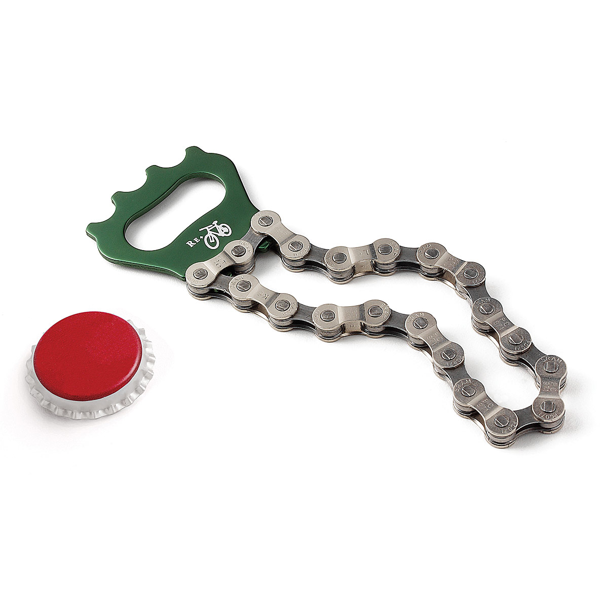
I started thinking about timing belts, especially something clever that Vik Olliver did on Rep Rap involving those ball chains used to switch ceiling lights on and off. I didn't really trust myself to be able to solder the ball chain together, and I continued scratching my head. Then I saw one of those bicycle chain bottle openers at a party, and realized that bicycle chain was the solution to my problem.

I started learning about roller chain and sprockets. It turns out sprocket tooth design is really pretty simple, much simpler than involute gear teeth, and I was able to design some sprockets with just a little study. It took a redesign because the first time, my stepper sprocket design assumed a friction fit would work, but when the part arrived, I discovered I'd need a set screw. In the picture to the left, I retrofitted a set screw on the initial sprocket design with sub-optimal results. This is probably adequate on a temporary basis, but an improved design is pending and should arrive by the end of August and should be in place for exhibition at Maker Faire.

 So this is the new design. I think it retains the Steampunk flavor of the original design, if perhaps not quite as pronounced. It's a bit simpler and all the plywood cutting can be done by hand with a compass and a jigsaw. So my design goal that it should be buildable by a person of minimal craftsmanship (like myself) is intact.

Barring some disaster, I expect to be exhibiting this printer (hopefully in operation) at Maker Faire NYC 2014, at the New York Hall of Science in Queens, on September 20th and 21st. If you're reading this, you're invited to come see it. If you can't make it, I'll try to post as much information here, on Github, and on Youtube as possible.

Wednesday, July 09, 2014

Cleaning up the SLA printer design

The stereolithographic printer described in my last post works, but it has a lot of room for improvement. Two obvious improvements are to use a stepper motor to raise and lower the build platform, allowing for automated operation, and to accept standard input files such as the STL file format.

In this post, I'd like to look at improvements in the overall mechanical design, specifically intended to make this printer easy for other people to build. I envision this as a printer that could be easily and affordably built by an after-school club, at a price of less than $600. The projector I used cost me $350 and I'll assume that's the same price for others. Likewise I expect others would pay about $75 for a couple of bottles of UV-cured resin. That leaves $75 for everything else. You have a stepper motor, a stepper control board, and a Raspberry Pi. I have a little wiggle room left for laser-cut plywood, and a 5-gallon bucket from Home Depot. I get my laser-cutting done at danger!awesome in Cambridge, MA. The bucket is bright orange, and that's the color I've used in this design, where the plywood is yellow and green (the green pieces having gear teeth that mesh). The pale blue stick-things are 1/4-20 threaded rods, cheaply available at Home Depot. The brighter blue thing is the stepper motor. The three green gears surrounding the threaded rods have captive nuts, allowing the stepper to raise and lower the threaded rods in lock-step. I'm kind of pleased with this design and I think this is what I'd like to show at Maker Faire NYC this year.
 

Looking down into the bucket, we can see one more circular piece of plywood which is the build platform. When we raise the three threaded rods high enough, the build platform comes up out of the bucket, which holds a layer of resin floating atop a salt water bath (a trick I borrowed from the Peachy Printer). And in fact, you could use this setup with a Peachy Printer rather than a projector, and you'd save money by doing so.

These gorgeous pictures are courtesy of Tinkercad.com. It's a pretty wonderful thing if you're doing 3D design. One last picture, showing the projector bouncing light off the mirror to illuminate the resin.


Sunday, July 06, 2014

Homebrew stereolithographic 3D printer

I've been interested in hobbyist 3D printers for quite a while. A friend of mine, Jeff Keegan has an exquisite blog about his several-year hobby of building RepRap-style printers. He has donated a printer to the Boston Museum of Science. I took a stab at starting a RepRap-style printer years ago, but my level of dedication was not equal to the task.

A RepRap-style printer (technically, a fused-deposition-modeling printer) works by squeezing molten plastic out of a hot nozzle onto the workpiece, where the plastic cools, forming the next vertical layer. One FDM printer can create some of the parts for another FDM printer, or to replace its own parts when they get worn. This was the idea behind the RepRap project, that partially self-reproducing printers could be very cheap.

Stereolithograhic 3D printers operate on a different principle, using ultraviolet light to cure resin. The video above illustrates this process.

The past few weeks I have been spending way too much time trying to figure out how to build a stereolithographic printer of my own. I looked at a lot of things other people have done and started doodling some ideas. A few times I made or purchased parts for a particular approach and later realized that it wouldn't work for some reason. But after a lot of tinkering, I finally produced the octahedron on the right.

My printer is pretty crude and is due for a lot of improvements in the days ahead. I had ordered a stepper motor controller board that didn't work, so I needed to manually rotate the threaded rod that lowers the workpiece into the resin bath.

Hopefully this picture isn't too confusing. A lot of this is stuff from the hardware store: a bucket, a lot of plywood, nuts and bolts, a piece of aluminum screen, a threaded rod, two straight rods. That black shape at the top held in place with a bungee cord is a pretty standard conference-room projector. When the thing is printing, the projector aims down into the bucket, which holds a quantity of resin floating on a much larger quantity of salt water. The ultraviolet light from the pattern projected onto the resin cures it in a particular shape, forming one layer of the product, and then the threaded rot rotates, moving the product down by one layer-height.

Currently I'm using a layer-height of 1/40th of an inch, which turns out to be quite visible to the naked eye, so I want to go down to something more like 1/100th of an inch.

I plan to post plans and software on Github and Instructables to enable anybody to build one of these printers for just a few hundred dollars. Most of the cost ($350) is the projector. I'd like to do the RepRap thing of using lots of pieces made by an identical printer, which would involve some redesign.

Tuesday, April 15, 2014

Espruino: JavaScript for embedded devices

My last post was really written primarily as background for this post. TL;DR: there is a lot we're doing right nowadays as software engineers, that we were screwing up badly 20 to 30 years ago.

I am moved to write this post because I've been playing with the Espruino board (having pre-ordered one during the Kickstarter campaign), which runs JavaScript close to the metal on an ARM processor.

JavaScript is a cool language because it draws upon a lot of the experience that engineers have gained over decades. Concurrent programming is hard, so JavaScript has a bullet-proof concurrency model. Every function runs undisturbed to completion, and communication is done by shared-nothing message passing. In the browser, JavaScript gracefully handles external events with unpredictable timing. That skill set is exactly what is required for embedded hardware control.

Crockford once referred to JavaScript as "Scheme with C syntax". JavaScript has many of the features that distinguish Lisp and its derivatives, and which set apart Lisp as probably the most forward-looking language ever designed.

This video is Gordon Williams, the creator of the Espruino board, speaking at a NodeJS conference in the UK. One of the great things he did was to write code that can run on several different boards. I'm particularly interested in installing it on the STM32F4 Discovery board because it costs very little and looks pretty powerful as ARM microcontrollers go. There is a Youtube playlist that includes these videos and others relating to the Espruino board.

A few decades' progress in computers and electronics

I got my bachelors degree in EE in 1981 and went to work doing board-level design. Most circuit assembly was wire-wrap back then, and we had TTL and CMOS and 8-bit microcontrollers. Most of the part numbers I remember from my early career are still available at places like Digikey. The job of programming the microcontroller or microprocessor on a board frequently fell to the hardware designer. In some ways it was a wonderful time to be an engineer. Systems were trivially simple by modern standards, but they were mysterious to most people so you felt like a genius to be involved with them at all.

After about 15 years of hardware engineering with bits of software development on an as-needed basis, I moved into software engineering. The change was challenging but I intuited that the years to come would see huge innovation in software engineering, and I wanted to be there to see it.

Around that time, the web was a pretty recent phenomenon. People were learning to write static HTML pages and CGI scripts in Perl. One of my big hobby projects around that time was a Java applet. Some people talked about CGI scripts that talked to databases. When you wanted to search the web, you used Alta Vista. At one point I purchased a thick book of the websites known to exist at the time, I kid you not. Since many websites were run by individuals as hobbies, the typical lifespan of any given website was short.

Software development in the 80s and 90s was pretty hit-or-miss. Development schedules were almost completely unpredictable. Bugs were hard to diagnose. The worst bugs were the intermittent ones, things that usually worked but still failed often enough to be unacceptable. Reproducing bugs was tedious, and more than once I remember setting up logging systems to collect data about a failure that occurred during an overnight run. Some of the most annoying bugs involved race conditions and other concurrency issues.

Things are very different now. I've been fortunate to see an insane amount of improvement. These improvements are not accidents or mysteries. They are the results of hard work by thousands of engineers over many years. With several years of hindsight, I can detail with some confidence what we're doing right today that we did wrong in the past.

One simple thing is that we have an enormous body of open source code to draw upon, kernels and web servers and compilers and languages and applications for all kinds of tasks. These can be studied by students everywhere, and anybody can review and improve the code, and with rare exceptions they can be freely used by businesses. Vast new areas of territory open up every few years and are turned to profitable development.

In terms of concurrent programming, we've accumulated a huge amount of wisdom and experience. We know now what patterns work and what patterns fail, and when I forget, I can do a search on Stackoverflow or Google to remind myself. And we now embed that experience into the design of our languages, for instance, message queues as inter-thread communication in JavaScript.

Testing and QA is an area of huge progress over the last 20 years. Ad hoc random manual tests, usually written as an afterthought by the developer, were the norm when I began my career, and many managers frowned upon "excessive" testing that we would now consider barely adequate. Now we have solid widespread expertise about how to write and manage bug reports and organize workflows to resolve them. We have test-driven development and test automation and unit testing and continuous integration. If I check in bad code today, I break the build, suffer a bit of public humiliation, and fix it quickly so my co-workers can get on with their work.

I miss the simplicity of the past, and the feeling of membership in a priesthood, but it's still better to work in a field that can have a real positive impact on human life. In today's work environment that impact is enormously more feasible.

Sunday, April 13, 2014

The whole Heartbleed thing

Lots of times, these reports are much more about theoretical possibilities than real events. The nature of this vulnerability is that attackers can get peeks at blocks of memory in servers. That memory is changing all the time as the server is doing stuff. It's a possibility that the block of memory happens to have a copy of your password or other information when the attacker grabs it.

Criminals who do these kinds of attacks will act on anything they find very quickly, because they know that victims will respond quickly by changing passwords, shutting off credit cards, etc. They would leave evidence if it had happened in any significant numbers, and there are places you could reliably find that evidence discussed (Bruce Schneier's blog, the EFF website) and the only mention is that certain big government agencies probably exploited the vulnerability, but it appears criminals probably haven't done so. The vulnerability existed for two years before it was publicly announced.

So the NSA has your passwords, but they probably had them anyway. The big question is, what information do you feel you MUST protect? Financials: online banking stuff, or credit card stuff, or your Paypal account, or the online access to your IRA or H&R Block. Medical: your doctor's patient portal website, any logins you have with hospitals or medical centers. Dating websites? Sexual fetish websites? I think I've exhausted the limits of my paltry imagination.

Those would be good passwords to change. You probably don't need to change your Facebook password, unless you're worried that NSA employees will get drunk and trash your Farmville farm.

More information at http://heartbleed.com/ but it tends to run to the rather technical. You can test any website's vulnerability using the tool at http://filippo.io/Heartbleed/.

Heartbleed is a buffer exploit, illustrated at http://xkcd.com/1354/. You tell the server you want some information which should be X letters long, but you ask for a much larger X, so that you get extra information from the server memory following what you asked for. The extra information might contain passwords and other profitable secrets.

Buffer exploits have been understood for years. What is supposed to happen is that the server's software should reject the too-large X value, but this stuff is programmed by fallible humans. Here is a very good (but pretty technical) explanation of the programming mistake.

Wednesday, December 11, 2013

ZeroMQ solves important problems

ZeroMQ solves big problems in concurrent programming. It does this by ensuring that state is never shared between threads/processes, and the way it ensures that is by passing messages through queues dressed up as POSIX sockets. You can download ZeroMQ here.

The trouble with concurrency arises when state or resources are shared between multiple execution threads. Even if the shared state is only a single bit, you immediately run into the test-and-set problem. As more state is shared, a profusion of locks grows exponentially. This business of using locks to identify critical sections of code and protect resources has a vast computer science literature, which tells you that it's a hard problem.

Attempted solutions to this problem have included locks, monitors, semaphores, and mutexes. Languages (like Python or Java) have assumed the responsibility of packaging these constructs. But if you've actually attempted to write multithreaded programs, you've seen the nightmare it can be. These things don't scale to more than a few threads, and the human mind is unable to consider all the possible failure modes that can arise.

Perhaps the sanest way to handle concurrency is via shared-nothing message passing. The fact that no state is shared means that we can forget about locks. Threads communicate via queues, and it's not so difficult to build a system of queues that hide their mechanics from the threads that use them. This is exactly what ZeroMQ does, providing bindings for C, Java, Python, and dozens of other languages.

For decades now, programming languages have attempted to provide concurrency libraries with various strengths and weaknesses. Perhaps concurrency should have been identified as a language-neutral concern long ago. If that's the case, then the mere existence of ZeroMQ is progress.

Here are some ZeroMQ working examples. There's also a nice guide online, also available in book form from Amazon and O'Reilly.

Saturday, November 23, 2013

What's up with Docker?

I've been hearing about Docker lately. Fair disclosure: I am no Docker expert. I've just tinkered with it a little bit so far and this post is part of my process of getting acquainted with it, and I'll probably update this post if I learn anything noteworthy.

It seems to be an interesting and useful wrapper for Linux Containers, a relatively new feature of the Linux kernel. Docker tries to solve the problem of providing a uniform execution environment across development and production.

In the Python world, virtualenv and pip create a sandbox with specific version numbers for various Python packages, regardless of what may be installed globally on the machine. Docker creates a sandbox of an entire Linux environment, much like a virtual machine, but much lighter-weight than a virtual machine.

Docker instances start in fractions of a second and occupy vastly smaller resources on your laptop or server than a virtual machine would. These days I work on a Macbook and run Linux in a virtual machine, and I'm told it will be practical to simultaneously run multiple Docker instances in the VM. So if you're somebody who's thought it would be fun to write software to run on multiple computers on a network but you haven't had the actual computers available, Docker is for you. I'm interested in Redis as a distributed task queue.

Thursday, October 31, 2013

Some favorite crowd-funded projects

There is a lot going on with crowd-funding these days. Over the past year or so, it has become huge. One might venture to say that it is a significant source of innovation in science, technology and art. Obviously there will be projects that cannot be crowd-funded; it is difficult to imagine a successfully crowd-funded Mars mission or cancer cure. But the space of feasible new projects is vast, and what follow are a few of my favorite crowd-funded projects.

But first, there is a recent noteworthy development from the SEC: previously allowed only to hand out rewards, crowd-funding campaigns will soon be able to award equity too. Equity had thus far been only for accredited investors, people with buckets of spare money in their garages and garden sheds. The possibility of investing in a successful venture rather than simply receiving a toy and a good feeling might make the already-fascinating crowd-funding scene a much more interesting place. It could play an important role in economic recovery.

OCULUS RIFT

The Oculus Rift is a virtual-reality headset representing an enormous improvement in performance-to-price ratio. The head tracking is smooth and the graphics are good. This is one of the first crowd-funded projects I heard about, and the first one I contributed to. For $300, I got a headset with a very entertaining demo, and if I get up the energy I will do something myself with science education.

By getting in early and having a huge success, the Oculus Rift set a precedent for big splashy projects, and probably helped Kickstarter as much as Kickstarter helped Oculus.

CastAR from TECHNICAL ILLUSIONS

CastAR is another virtual reality gadget, this time a pair of glasses that project an image onto a retroreflective surface in front of the user. One big innovation here is that the virtual reality can be mixed with actual reality, for instance using game pieces or other objects. Also, because the user is looking at things some distance away, eye strain is reduced. The head-tracking on CastAR follows both rotation and translation where the Oculus Rift only follows rotation.

BLEDUINO

This is a Bluetooth-enabled Arduino board. Arduino is a cheap easy-to-use controller board for hobbyist projects and art installations. With Bluetooth, whatever you're building can connect to a phone or tablet.

ESPRUINO

The Espruino is another Arduino-based controller board. What's unique is that it is designed to operate with a language called JavaScript, which has been used in web browsers for a long time but has slowly been gaining momentum as a hardware control language.

CHINEASY

This is an instructional program to teach yourself Mandarin. There are flashcards and animations to learn the written characters, and audio materials to learn the spoken language.

STAR TREK: RENEGADES

If you miss the pre-J-J-Abrams Star Trek franchise, this is for you. This movie brings back Walter Koenig (Chekhov from the original series) with several actors from Star Trek: Voyager. It is set ten years after Voyager's return to human space, and politics and hilarity ensue.

PEBBLE SMARTWATCH

Another big success story, the Pebble can now be purchased for $150 at Best Buy. It connects to your phone and can run Android apps on a very small screen. It has a magnetometer (compass), a three-axixs accelerometer, Bluetooth, ambient light sensors, a 144x168-pixel screen, and a week of battery life between charges. It connects via Bluetooth to your phone so the phone can stay in your pocket most of the time.


My long list below includes some projects that were already funded and have gained significant fame, like the Oculus Rift virtual reality headset, or the Pebble smartwatch now available at Best Buy.

Random projects

Phone and tablet

Electronics and computers

Robots and Flying Things

Gaming

Maker stuff

Here's an interesting list of crowd-funding resources: http://crowdfundingforum.com/showthread.php/6748-List-of-All-Crowdfunding-Sites-and-Platforms-Ever-Expanding

The shortened URL for this post is http://goo.gl/ehfBQb.

Friday, October 25, 2013

Bar Camp Boston 2013 talk on automation of science

This is an outline for a talk I gave at Bar Camp Boston 8 on the automation of science. It's a topic I've blogged and spoken about before. The shortened URL for this post is http://goo.gl/rv3Xik.

In 2004, a robot named Adam became the first machine in history to discover new scientific knowledge independently of its human creators. Without human guidance, Adam can create hypotheses to explain observations, design experiments to test those hypotheses, run the experiments using laboratory robotics, interpret the experimental results, and repeat the cycle to generate new knowledge. The principal investigator on the Adam project was Ross King, now at Manchester University, who published a paper on the automation of science (PDF) in 2009. Some of his other publications: 1, 2, 3.

Adam works in a very limited domain, in nearly complete isolation. There is plenty of laboratory automation but (apart from Adam) we don't yet have meaningful computer participation in the theoretical aspect of scientific work. A worldwide scientific collaboration of human and computer theoreticians working with human and computer experimentalists could advance science and medicine and solve human problems faster.

The first step is to formulate a linked language of science that machines can understand. Publish papers in formats like RDF/Turtle or JSON or JSON-LD or YAML. Link scientific literature to existing semantic networks (DBpedia, Freebase, Google Knowledge Graph, LinkedData.org, Schema.org etc). Create schemas for scientific domains and for the scientific method (hypotheses, predictions, experiments, data). Provide tutorials, tools and incentives to encourage researchers to publish machine-tractable papers. Create a distributed graph or database of these papers, in the role of scientific journals, accessible to people and machines everywhere. Maybe use Stackoverflow as a model for peer review.

Begin with very limited scientific domains (high school physics, high school chemistry) to avoid the full complexity and political wrangling of the professional scientific community in the initial stages. As this stuff approaches readiness for professional work, deploy it first in the domain of computer science and other scientific domains where it can hope to avoid overwhelming resistance.

Machine learning algorithms (clustering, classification, regression) can find patterns in data and help to identify useful abstractions. Supervised learning algorithms can provide tools of collaboration between people and computers.

The computational chemistry folks have a cool little program called Babel which translates between a large number of different file formats for representing molecular structures. It does this with a rich internal representation of structures, and pluggable read and write modules for each file format. At some point, something like this for different file formats of scientific literature might become useful, and might help to build consensus among different approaches.


A treasure trove would be available in linked patient data. In the United States this is problematic because of the privacy restrictions associated with HIPAA regulation. In countries like Iceland and Norway which have universal health care, there would be no equivalent of HIPAA, and those would be good places to initiate a Linked Patient Data project.