Friday, February 22, 2008

Too-brief overview of DNA nanotechnology

cube.gifA lot of interesting work has been done with DNA nanotechnology, much of it starting with Nadrian Seeman's work on DNA polyhedra in the mid-90s (1, 2).

Around 2000, Andrew Turberfield (Oxford University's Department of Physics) used DNA to make tweezers, with arms 7 nanometers long.
"Of course it's all very speculative," said Dr Turberfield, "but you can imagine, for instance, little factories on chips doing chemistry or simple assembly. You can think of production lines made up of little motors with different reactants being passed from one place to the next."
Things got really interesting in March 2006 with Paul Rothemund's DNA origami technique. Here is the publication. I was working at Nanorex at that time, and we were all quite excited about it.

dna_tetrahedron1_256.png
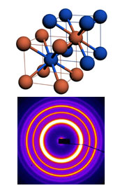
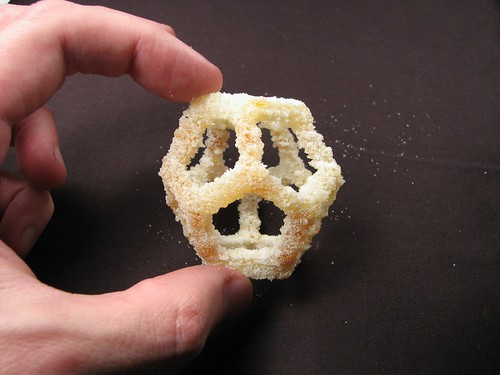
In 2005 Turberfield and colleagues described a family of DNA tetrahedra consisting of triangles of DNA helices covalently joined at the vertices to form a mechanically rigid 3D structure. This image of a reduced model of one structure, which is less than 10 nanometers on a side, was created using NanoEngineer-1 Alpha 9. The bowing of the DNA helices is pronounced in this rendering and is the result of electrostatic potential terms included in the customized molecular-mechanics-like force field developed by Dr. K. Eric Drexler specifically for DNA structures. Regarding Turberfield's work, New Scientist wrote:
Now Andrew Turberfield [et al] have shown how carefully crafted DNA structures can be made to self assemble and change shape when sent specific DNA signals. The researchers built tetrahedrons ... using four short DNA "struts" that join at each end. The process exploits the way DNA is held together by complementary bases that form the rungs of a ladder-like structure ... the researchers made cages with two extendible struts that could be independently controlled using different DNA sequences. In theory, it should be possible to create cages in which every strut can be controlled independently, Tuberfield says.
These cages are a combination of support material and linear motor, and with the many other DNA tricks being done, they should allow people to build large, complicated, reasonably rigid 3D structures that have controllable moving parts. So this is a very promising development.

A very recent announcement of work by Chad Mirkin and colleagues. They have found a way to use DNA to glue together arbitrary arrangements of teeny gold spheres. People have known for some time now how to make DNA stick to gold spheres, and by careful selection of DNA sequences, Mirkin et al can position groups of spheres in almost any 3D configuration they want.

In light of these developments, Nanorex has narrowed its focus from "general" nanotechnology (anything one might build from common small molecules) to structural DNA nanotechnology. This is likely to be where much progress will occur in the next five years or so. I hope Nanorex will still be around after that, and will be in a good position to shift gears as we move beyond DNA to more general chemistry.

Sunday, February 17, 2008

Those commercial 3D printers sure are gittin' purty

Some commercial 3D printers are very pretty. This one prints in colored plastic and is intended to create prototypes in a few hours that can be shown to managers or customers. The claimed resolution of this thing (presumably in all three dimensions) is 450 dots per inch. Drool.

In twenty years, all the patents for this printer will have expired, and it will be possible for hobbyists to make such pretty stuff at such high resolution. Hmm, thinking more about that inclines me to start an economics blog, since I blog about economics a lot elsewhere.

Friday, February 15, 2008

An XYZ platform for fabbing or CNC

I was watching an auction for a CNC XYZ table on eBay that went for $300, item number 200198037915. I would have bid on it if the Z travel hadn't been only 2 inches. It was built from plans from hobbycnc.com and didn't have stepper motors or the machining tool but was otherwise complete. I felt lust in my heart, but that itty bitty Z travel bugged me, so I thought about what could be done to increase it. Here's my general idea.


My hope is that the blue-hatched stage can be made to take either a Dremel tool for CNC milling, or an extruder for fabbing. The result might or might not be self-replicative in a RepRap sense but it would be a cool toy.

Monday, February 11, 2008

RepRap is now half-way to replication

Vik Olliver has made good progress (1, 2, 3) on the goal of self-replication for the RepRap, having now been able to use a RepRap to fabricate half the RepRap's parts.

It's interesting that you can see the size of the volume pixels Vik is working with. These pieces were printed with polylactic acid, I believe.

Unrelated but cool: Kovio is a non-hobbyist company working on a process to inexpensively print working transistors. Early applications will include smart cards, later you'll see wall-sized displays.


Also unrelated but also cool: Fernando Muñiz has been working with UV-cured resins. This will work a bit like the CandyFab, except the uncured resin is still a liquid so under-support structures are still required. Interesting, I'm not sure if it's better or worse than the FDM approach used by RepRap, Fab@Home, and Tommelise. Also, I don't have any idea how environmentally benign these resins are; it's hard to imagine they're as green as polylactic acid.

Saturday, February 09, 2008

Big fabbers: houses, boats, factories

How big could a fabber get? Could a fabber build a boat or a house? Here are two big CNC machines, one of which is claimed to do work on boat hulls.


A fabber placing individual drops of building material would be awfully slow for a very large project. One work-around would be to trade away spatial resolution, and let the fabber lay down big handfuls of wet concrete.

Maybe you'd want many fabbers feeding small pieces to an assembler that assembles them into bigger pieces. The assembler must be able to make the small pieces stick together, by gluing them or melting the sides or by using mechanical fasteners such as screws or nuts and bolts. It's possible that the big pieces might then be assembled into very big pieces, and again an assembling machine must be fed from many sources. The assembler would need to be very smart to recognize and correct assembly errors, and would probably need machine vision. This would work well for products from a factory, but might be unsuitable for a house.

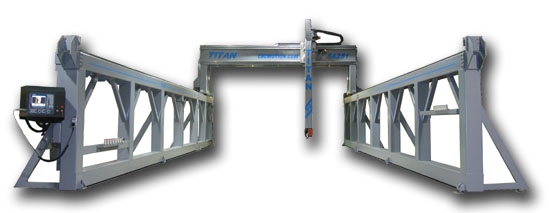
A google search for "robot bricklayer" turns up a few modest research efforts. I would have imagined something like the big XYZ stage above with a brick-lifting robot arm, wheeled into position over the site of the future house, but the most advanced effort visible on the web is a standard industrial robot arm picking up bricks instead of doing whatever else robot arms normally do. The arm can't move around the entire volume of the future house, it's not on any sort of XYZ stage, it's just bolted to the floor like any other industrial robot arm. So robotic house construction is still quite a ways off.

Thursday, February 07, 2008

Fabbers as tissue engineering tools

In late 2006, Gabor Forgacs and other researchers pioneered tissue engineering techniques using 3d printers. This obviously is not a hobbyist application but it's very interesting, and could save thousands of lives. The technique involves alternate layers of "biopaper" and "bioink", the former being a temporary scaffolding gel and the latter being a suspension of adult stem cells.

Tommelise project

Tommelise is Forrest Higg's attempt to build his own RepRap-like gadget before RepRap itself is ready for wide distribution. He has spoken at an O'Reilly conference about the RepRap project and he has some fascinating ideas about architecture and how fabbers might relate to it. The recent (early Feb 2008) postings in his Tommelise blog describe his success in connecting stepper motor axles to threaded rods, something I had been wondering about myself.

In the Tommelise FAQ, Higgs mentions Linux and Java (which have been adopted by the RepRap project) as presenting a steep learning curve to people without a software background, citing Microsoft Windows and Visual Basic as more user-friendly alternatives. My own early experiences with Linux required enormous patience. Higgs writes Tommelise has been created for people who aren't particularly clever and may be living in modest circumstances. Any open-source "fabber revolution" (1, 2, 3) will be an empty exercise if it fails to serve such people. Then again, if a genuinely open-source revolution is to occur, we'll eventually need to wean ourselves from Microsoft and make our own tools equally user-friendly.

Wednesday, February 06, 2008

Interesting Russian project

Here's the website in Russian, and a Google translation to English (click on the "Constructor Kulibin" link). I found this referenced from MAKE Magazine. This is a very interesting project.
They have a great-looking XYZ stage built from a CNC kit. They lower a heating element onto powdered raw material, sintering the raw material as the CandyFab does, except their heating element is a length of nichrome wire instead of a jet of hot air. It gets hot enough to glow, and on the web page they mention that they can work with any powdered material with a melting temperature from 100 to 300 Celsius, including sugar, wax, "Plexi" (plexiglass?), and mixtures such as plastic and sand, plastic and metal powder, powdered paint and sugar powder. Like the CandyFab, each layer of fresh material is laid down on top of the previously worked layer (and I hope that process is automatic as it sounds tedious otherwise) and then you scribble a cross-section on the new layer with the heating element, and then it's time to put down another layer.


The nice thing to this kind of approach is that the unmelted/unfused material provides mechanical support for the built structure. You can build shapes that RepRap and Fab@Home can't make, such as bridges or inverted cones, because any bridge-like part that will go over empty space is built with stuff under it to support it.

This made me curious to start looking around at CNC kits, which could nicely jump-start any fabber project. The XYZ machinery for a fabber is called a "gantry" in CNC language, and there is a very active hobbyist CNC community. Here is a video for a CNC gantry kit that somebody was selling for $195 on eBay. The video itself is for sale ($20) so this is just a teaser.


Here's a few interesting CNC links.

Friday, February 01, 2008

Make Controller Kit

The Make Controller Kit is a pair of boards that snap together, with a AT91SAM7X256 as the microcontroller. For communication it has USB, Ethernet, CAN, and JTAG, and supports the Open Sound Control protocol, which has interfaces for numerous programming and scripting languages. It offers eight analog inputs with 10 bits of precision over a 0-to-3.3-volt range. There are eight high-current digital outputs that can drive relays or two stepper motors or possibly solenoids. There are four servo controllers. It has an 8-position dipswitch. It costs $109 at the on-line store for Make Magazine.

Wednesday, January 30, 2008

CandyFab: The Revolution will be Caramelized

Here's a PDF presentation about the CandyFab, an unusual approach to a hobbyist fabber. These guys decided they could relax their spatial resolution in favor of large volume and cheap fabbing materials. Their fabbing material of choice is sugar, much cheaper than the plastics used by RepRap. Some of the things they make are considerably larger than can be made with RepRap. Here's a Flickr photo set.

In September the CandyFabbers came up with a better hot air nozzle that gives them considerably improved spatial resolution, with volume pixels of about 1/16 inch instead of 1/5 inch.

Some MIT folks have built a fabber that makes stuff out of pasta dough.

Tuesday, January 29, 2008

How does one get started?

How does one start to build one's own fabber? RepRap and Fab@Home both offer instructions. There is of course the caveat that the technology is new and experimental and bleeding-edge, so it's not a shrink-wrapped thing where you simply tear open the packaging and start using it. My goal in this posting is mostly to decide whether it makes sense for me to start work on a fabber. My early conclusion is that I'd like the field to mature a little bit more, but it might be fun to tinker with just the 3-axis motion part (check out the video), probably using this microcontroller board.

The RepRap folks have a page about constructing their version 1.0 fabber, called "Darwin". They recommend that you join the RepRap Research Foundation, which supports new fabber builders, and you can purchase parts from their on-line store.

Fab@Home has a Getting Started page with links to their catalog and the list of materials that you can fab with. A pre-assembled Fab@Home fabber will set you back about $3600 plus shipping, currently with a 6-to-8 week lead time, so I guess people are buying them. The Fab@Home is an impressive thing, and good looking.

Hobbyist fabbers today look the way Linux did in 1993. In five or ten years fabbers will be much more common and much more polished, but the people tinkering today will have 99% of the fun. Linux in 1993 was not at all user friendly, everything needed to be hand-tweaked, and you needed to understand a lot of it to use any of it, and the same was true with cars in 1910, and with fabbers now.

Brilliant RepRap video (thanks to Emeka Okafor)

I am deeply indebted to Emeka Okafor, author of the Timbuktu Chronicles blog and director for the TEDGlobal 2007 conference in Tanzania, for stumbling across this brilliant Poptech video of Professor Adrian Bowyer, the inventor of the RepRap fabber. I would also like to thank Mr. Okafor for giving attribution to my nanotechnology blog, and call attention to his postings on technologies that can help Africa and other developing regions. There is an Emeka Okafor who plays basketball, I'm not sure if it's the same guy.


Bowyer talks about the economics behind the project, particularly its ability to empower communities that are now economically depressed. There is some yummy game-theory stuff in the paper linked here that does not get mentioned in the video, check it out. He also talks about using polylactic acid (wikipedia) as a printing material for the RepRap. This is significant because you can make PLA from starchy vegetables like potatoes and corn, and when you're finished using your PLA object, you can compost it to help grow next year's crop of starchy vegetables. You can have a closed-loop local manufacturing economy that doesn't require trucks or trains or ships to move products around. In fact there are several materials under consideration, and thought has been given to printing a single product from multiple materials. The Fab@Home folks also have an impressive list of materials that can be fabbed, including chocolate.

I got curious about PLA and did a little googling. In a RepRap forum there is a discussion of just how easy it is to turn starchy vegetables into PLA. From the sound of it, it is non-trivial and demands that the person attempting it be quite knowledgeable. One person compares "home PLA production today to home biodesiel production 20 years ago, when it was arcane, a little dangerous, and rare, but theoretically possible" and notes that for many people it will simply not be economical compared to mail-ordering some PLA. I found a place that sells utensils, plates, and cups made from PLA. NatureWorks appears to be a source for PLA in ready-to-work form.

3D printer in a knick-knack store

Make Magazine has a note about an Umbra concept store in Toronto which now has a 3D printer (some people also call them "fabbers"). The store can use it to fabricate novel items, and the store chain designers visit the store to create and fabricate designs while chatting with customers about the process. The little white widgets to the left of the printer are some of its products.


I'm interested in 3D printers, but I haven't dedicated the time to build my own, as some people have started to do. It's intriguing to imagine what 3D printers might accomplish in combination with automated design techniques such as genetic algorithms (here are some more GA links).

At the present time, 3D printers are the closest things to real nanofactories, and they present limited versions of many of the same challenges that nanofactories will bring, such as copyright issues and the bumpy ride toward a post-scarcity economy.

Monday, January 28, 2008

Starting a fabber blog

Lately I've been thinking and posting a bit about fabbers (also called 3D printers), primarily on my nanotechnology blog. I think the topic (and my growing interest in it) is rich enough to deserve its own blog. I am particularly interested in affordable hobbyist fabber projects, something I might be able to fool around with myself.

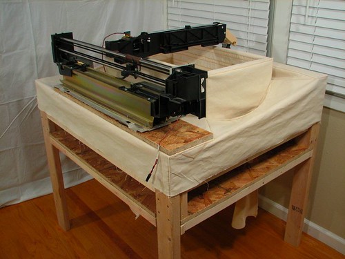
The fabber idea is pretty simple. Take a hot glue gun and three stepper motors. Use the stepper motors under computer control (with appropriate mechanics) to position the hot glue gun at a specific XYZ point, and deposit a drop of hot glue. The glue cools and you move to the next XYZ point. Use this arrangement to draw a glue pattern on a horizontal surface, then move up a little bit and draw the next layer, and then the next. Soon you've got a 3D object of almost any shape you wish. A few of the details can vary -- it's not really glue, it's typically a polymer like polylactic acid -- but that's the basic idea.

There are professional and industrial fabbers with prices starting at about $50,000. But more interestingly, there are hobbyist projects to build much more affordable fabbers. The two currently prominent hobbyist efforts are the RepRap project (wikipedia entry) started by Adrian Bowyer at the University of Bath in the UK and the Fab@Home project started by Hod Lipson at Cornell. There are others but these two have the highest visibility and, as far as I can tell, the largest numbers of participants.

The Fab@Home fabber looks more polished than the RepRap, but I find the RepRap more interesting. Partly because it's more affordable (a getting-starting price somewhere around $400 versus $2300) but also because Bowyer is more committed to an open-source approach and is more interested in the implications of that approach. He very intentionally designed a machine that could fabricate most of its own parts and could therefore mostly copy itself. If the machine becomes popular, its price will quickly drop (building one today might cost a good deal more than $400 and a very large investment of tinkering time) to roughly the price of the few non-copyable parts and the raw plastic for the rest.

Sunday, January 27, 2008

Videos and links, RepRap and Fab@Home

Since I've been writing a lot about fabbers lately, I've decided to start a fabber blog and start migrating my fabber postings over to it, starting with this one. Fabbers are only peripherally related to advanced nanotechnology (the economics look similar) and I'd like the fabber blog to go into a level of detail that's not appropriate here.

As far as economic similarities, a fabber looks a lot like a crude nanofactory, and raises many of the same societal concerns but in a smaller, safer way. One of the popular speculations about mature nanotechnology goes like this: (1) sufficiently advanced nanofactories will be able to make almost any desired product from materials found in nature, so (2) the price of physical goods drops to nearly zero, and then (3) money ceases to exist and we all live in a post-scarcity society free of poverty, disease, and war.

It's an appealing simple notion, probably too simple. Even when the necessities of life are available essentially for free, humans always envy other humans and there will still be a premium to pay for things beyond the survival level. Economic demand will exist as long as we're still human, and money will too. Besides, physical goods aren't the only things we spend money on. I can imagine a robot bus driver at some future time, but a robot doctor seems a long way off, and it's hard to imagine the board of directors that will appoint the first robot CEO.

Tuesday, January 01, 2008

Xilinx Spartan 3 FPGA eval board

I was thinking I wanted to do something with the ARM91SAM7 eval board and a Xilinx FPGA, and I discovered that Xilinx also sells a eval board for their Spartan-3 FPGAs for $150. Here's the user guide (PDF). Big surprise, it's available at Digikey.

The Spartan-3 series has hardware multipliers, blocks of RAM, and "distributed RAM bits" which you can spread around your design as needed. Pretty sweet. As I mentioned in an earlier posting, there are readily available HDL tools for FPGA design on a Linux platform. Hardware design shouldn't necessitate the indignities of Windows.

Here is a ridiculously affordable SAM7 board that I need to investigate. It lacks RS-232 level converters, and you need to kludge the JTAG stuff (probably drive it with a parallel port somehow or other). Also interesting are these two open-source simulators for the ARM7 architecture.

The idea would be to use the SAM7 eval board to program the FPGA on the Spartan-3 eval board. FPGA programs are pretty large, so maybe this should be done by feeding the bits through the USB cable. Then you have some GPIO bits on the SAM7 connect to IO pins on the FPGA, and other IO pins on the FPGA to the outside world.

Some years ago, there was a guy who got his hands on some prototyping hardware of this sort (PowerPC based, I think I recall) and he set up a paid-subscription website where subscribers could submit compiled code and run it on his hardware. The cost of a subscription was small compared to the price of buying one's own hardware. According to EE Times Asia, Hitachi was doing the same thing in 2002.
Hitachi Semiconductor America Inc. is trying to move remote engineering to the next level by letting customers tinker with microcontroller hardware and software tools via a Web browser.

Working with DevelopOnline, Hitachi has set up several remote development stations for its H8 microcontroller family. For a fee, engineers can access these remote engineering laboratories from a PC at any time. Hitachi launched the service with its H8/3664 microcontroller device and plans to expand the program during the next several months to include other members of the H8 line and the company's SuperH devices.
One could make two of these gadgets and connect one to an Apache box to set up a remote development website like this. The second gadget is used to tweak/observe GPIO pins, interact with serial debug, etc. There would need to be some mechanism for allocating time fairly among multiple subscribers. The website would want lots of example code (or pointers to code findable on the web) for people to get started.

Thursday, December 27, 2007

AT91SAM7S microcontroller and eval board

Recently I came across the AT91SAM7S microcontroller from Atmel (Wikipedia article). It's a very cool gadget and is affordably available at Digikey. Here is Atmel's ad copy:
The AT91SAM7SE512 is a Flash microcontroller with external memory bus based on the 32-bit ARM7TDMI RISC processor. It features 512K bytes of embedded high-speed Flash with sector lock capabilities and a security bit, and 32K bytes of SRAM. The integrated proprietary SAM-BA Boot Assistant enables in-system programming of the embedded Flash. The external bus interface supports SDRAM and static memories including CompactFlash and ECC-enabled NAND Flash.

Its extensive peripheral set includes a USB 2.0 Full Speed Device Port, USARTs, SPI, SSC, TWI and an 8-channel 10-bit ADC. Its Peripheral DMA Controller channels eliminate processor bottlenecks during peripheral-to-memory transfers. Its System Controller manages interrupts, clocks, power, time, debug and reset, significantly reducing the external chip count and minimizing power consumption.

In industrial temperature worst-case conditions, the maximum clock frequency is 48MHz. Typical core supply is 1.8V, I/Os are supplied at 1.8V or 3.3V. An integrated voltage regulator permits single supply at 3.3V. The AT91SAM7SE512 is supplied in a 128-lead LQFP Green Package, or a 144-ball LFBGA Green Package. It is supported by an Evaluation Board and extensive application development tools.

The AT91SAM7SE512 is a general-purpose microcontroller, particularly suited to applications requiring high performance, USB connectivity and extended on- and off-chip memory.
So that's already pretty cool, but even better, there is a great little evaluation board which is also available at Digikey. Software resources abound.

Thursday, December 20, 2007

Other great nanotech (and related) blogs

I guess if I say "other great" nanotech blogs, the implication is that my blog is itself great, but many of these listed are much better than mine. The people doing them put in more work and more thought. Not all of these are relevant to long-term nanotech, but anyway here's the list.
  • Tom Moore's Machine Phase blog -- Tom is now working for Nanorex, and doing a lot of pretty, brilliant nanomachine design work.
  • Damian Allis's Somewhereville blog -- Damian is Nanorex's consulting quantum chemist, and a fascinating guy in general. He doesn't play a scientist on TV, he's an actual real scientist.
  • Gina "Nanogirl" Miller's blog needs no introduction for those who've been around nanotech discussions for a while
  • Blog of the Center for Responsible Nanotechnology
  • Howard Lovy's NanoBot blog
  • Foresight Institute's Nanodot blog
  • Rocky Rawstern's blog
  • A list of nanotech blogs
  • An explanatory website (not a blog per se) by one of the authors of "Nanotechnology for Dummies"
  • A blog about nanocrystals, though I'm not sure what differentiates a nanocrystal from any other crystal
  • The Singularity Institute is primarily about artificial intelligence rather than nanotechnology but there is a lot of common ground.
  • The IEEE has an automation blog about present-day industrial robots.
  • Another present-day robot blog, this one with more of a hobbyist spin.
  • Emeka Okafor's Timbuktu Chronicles blog is not about nanotechnology or robotics, it's about technologies that help and empower people in developing regions of the world. When not blogging, Okafor sometimes plays basketball, unless it's another guy with the same name.

Tuesday, December 11, 2007

The Roadmap Report is published!

The report is now available in PDF format. If you are a Digg subscriber, PLEASE vote up the digg story about it so it reaches the front page. Publicizing the report is a step toward a rational and benign development policy for advanced nanotechnology. I have the privilege of knowing a few of the people who've been involved with the Roadmap project, and they are the kind of people you hope will be involved: very bright, and very ethical.

I haven't gotten far in reading the report yet myself. It's rather thick, in two sections of about 200 pages each. Don't be put off by that, as the language is quite accessible, even in the more technical second half.

Monday, October 22, 2007

Brilliant collection of hobby electronics videos

http://dev.emcelettronica.com/ETUBE

This is a collection of YouTube videos about different topics in hobby electronics. I've only just discovered this and haven't yet checked out many of the videos, but it's great to see that so many have been posted. It seems to mostly be two guys working for Make Magazine.

Thursday, October 18, 2007

It's a good time to be an electronics hobbyist

OurPCB is a Chinese PCB fab outfit with an initial cost of $57.00 and a subsequent charge of around 15 to 25 cents per square inch for 2-layer boards and 50 to 75 cents per square inch for 4-layer boards. The per-square-inch costs shrink for bigger orders. So PCB fab and assembly is cheap. What do I do with this? Obviously there is a huge opportunity to do something.

PCBs and assembly (even surface mount assembly) are no longer a significant obstacle to complex electronic projects. The next obstacle is that I'm lazy about learning. To some extent that can be addressed by prioritizing what to learn - if USB does all the communication I need, I can ignore PCI.

We could have an electronics hobbyist renaissance as good as the 1970s, starting with a series of articles in Make magazine. O'Reilly would probably love it.

The economics works better for big boards than for small boards. I can envision scalable VLIW array processors spanning several FPGAs, or maybe tightly networked DSPs or GPUs. I like the look of the Analog Devices ADSP-31362. I could review some of the molecular modeling code out there (Amber, CHARMM, Gamess, Gaussian, Gromacs, NAMD) and build an scalable architecture optimized for molecular modeling, large-scale simulations, and other interesting things.

Building a supercomputer, that's so unimaginative. I don't have any interesting problems to feed it. I suppose I could build it and let other hobbyists figure out what problems to throw at it.

Wednesday, October 17, 2007

Some of the code for the board

Much of this code was written by a genius named Wolfgang Wieser, who deserves the Nobel Prize in hobbyist electronics. I've tweaked his code in places.

The firmware is at http://will.ware.googlepages.com/fx2_firmware.tgz and the Eagle design files are at http://will.ware.googlepages.com/n1ibt_board.tgz.

I work in Linux, and the stuff in these tarballs is written to work on a Linux box. To build the firmware you'll need SDCC on your machine. I've built the firmware successfully on Mandriva 2006 and Fedora Core 5. I have had trouble getting it to work on Ubuntu and hope to get that fixed because I'm migrating my home machines to Ubuntu.

Verilog/FPGA tools for Linux

Until I get more organized with this, it's just a collection of random links. I'll need to figure out a way to program the FPGA on my board.Go to the Xilinx web page for downloading WebPACK and grab a free download. It's a shell script; run it to install the Xilinx tools on your hard disk. It will take about a gigabyte so make sure to install it in a partition with that much room. Start reading doc/usenglish/books/docs/qst/qst.pdf. That's as far as I've gotten today.

Good Verilog tutorial here.

More about the board -- progress stalled, hoping to pick it up again

Periodically people email me and ask how things are going with my SDR board. Things are quite thoroughly stalled. I can program the FX2 over the USB cable, and I can wiggle the I/O pins, and I've connected the I/O pins to the FPGA's JTAG programming pins. Theoretically it should be pretty easy to program the FPGA after that. But that's where it is stalled; for some reason the FPGA won't program correctly. Go figure.

One thought is to make up a board with a lot more testpoints, like this.

This design is for a temporary two-layer board that I would use only to get the design and development effort back on track. Once I'd resolved the FPGA programming issues, I'd go back to a four-layer design with a lot fewer testpoints.

But if you're one of those impatient folks who wants to play with a software-defined radio RIGHT NOW then you should check out these links, many of which describe projects that are much further along than my board.

The software-defined radio board (an old post)

Two years after my first attempt, I am working on a new board for software-defined radio. In the past, I pursued this as a political agenda, but that made me rush, and ultimately design a crummy board that didn't work. I've split the design into two pieces and this board is the first piece. It has an 8-bit processor with USB slave capability, and it has a Xilinx XC3S400 FPGA with 400K gates, lots of on-chip RAM, and 16 hardware multipliers, each 18-bit by 18-bit. The USB channel can get data to or from your laptop at over 50 megabytes per second. The board has 46 general purpose I/O pins and six dedicated pins. Not counting assembly, which you can do cheaply at home, the board costs about $70, so it's a pretty good deal for a hobbyist.

The second piece of the radio is a board with fast digital-to-analog and analog-to-digital converters, to translate the signals between the digital domain and the world of radio electronics. A receiver would use an ADC, a transmitter would use a DAC. I'd like to design a receiver board first, but I want to get the USB/FPGA board up and running before that.

If you had this thing connected to your laptop, you'd install GNU Radio and you could transmit and receive radio signals. Depending on the analog hardware you had, you could do this on any of several radio bands, and with the USB bandwidth and a fast ADC, you could pull in whole television signals, maybe even HDTV signals. And that's when things get interesting politically, because that's the battleground for fighting the Broadcast Flag battle.

The USB/FPGA board is a remarkable example of what a low-budget electronics hobbyist can do these days. A couple years ago I spent some money on a license for CadSoft Eagle to do four-layer boards but I expect it to fill my hobbyist needs for a long time. Now I can send my Gerber files to PCB fab outfits in China like this one and get boards for ridiculously low prices. As a result, my electronics projects cost very little more than the price of the parts. It's cool, and it calls for a renaissance of electronics hobby activity. To us oldtimers it seemed like the 1970s was the peak for that kind of thing, but it can come back stronger than ever.

Monday, October 01, 2007

Things are a little different for Ubuntu

On an Ubuntu box I needed to change my 1xEVDO files. Now /etc/ppp/peers/1xevdo look like this.
-detach
ttyACM0
115200
debug
noauth
defaultroute
usepeerdns
connect-delay 10000
user 5089547611@vzw3g.com
show-password
crtscts
lock
lcp-echo-failure 4
lcp-echo-interval 65535
connect '/usr/sbin/chat -v -t3 -f /etc/ppp/peers/1xevdo_chat'
And /etc/ppp/peers/1xevdo_chat looks like this.
TIMEOUT 10
ABORT 'NO CARRIER'
ABORT 'BUSY'
ABORT 'NO DIALTONE'
ABORT 'NO ANSWER'
ABORT 'ERROR'
SAY 'Starting CDMA modem script\n'
'' 'ATZ'
'OK' 'ATE0V1'
OK-AT-OK 'ATDT#777'
CONNECT \d\c
That seems to do the trick. This stuff was cribbed from an article at Linux.com. It seems to work a good bit better, actually, so I should probably try this on the FC5 box as well.

Friday, September 28, 2007

Verizon phone as cellular modem

In a week or two I will be traveling. There will probably be Verizon coverage but there won't be conventional internet access. So I picked up a USB data cable for my LG VX8300 and added Verizon's BroadbandAccess connectivity to my account for a month. I'm a big Linux snob, so I needed to dig around for relevant Linux info. I found everything I needed on KA9Q's web page on the subject.

On Fedora Core 5, I needed to set up three files:
  • /etc/ppp/peers/1xevdo
  • /etc/ppp/peers/1xevdo_chat
  • /etc/ppp/pap-secrets
  • /etc/resolv.conf # use known-good nameservers
and then run
pppd call 1xevdo
as root. Within a few seconds, you should see a valid IP address when you type
ifconfig ppp0
and you're online. It's the coolest thing. Considerably slower than the wireless service at Starbucks or Panera but it's a lot better than no connectivity at all.

Tuesday, September 11, 2007

The Roadmap conference is coming up

A couple years ago, Foresight, Battelle, the Society of Manufacturing Engineers and a few other organizations put together a project called the Technology Roadmap for Productive Nanosystems. The idea was to figure out the steps that would lead us to a world of safe and mature nanotechnology. I know some of the people involved in this effort. They've had meetings to which I've not been invited, which is appropriate because they have important work to do, and they don't want the distraction of answering questions from the idly curious.

Their work has percolated along for about two years (that I've been aware of, probably more time before that) and finally there will be a conference where they will tell the world what they've been up to. As luck would have it, I have a schedule conflict and will be unable to attend, but there will be a CDROM of the presentations and I hope to ask around and see if I can get a copy.

I have high hopes for the work these people have done. This is a well-organized effort by a lot of very smart people with a wide range of relevant expertise.

The Center for Responsible Nanotechnology website discusses the societal risk of multiple competing nanotechnology development efforts:
The existence of multiple programs to develop molecular manufacturing greatly increases some of the risks listed above. Each program provides a separate opportunity for the technology to be stolen or otherwise released from restriction. Each nation with an independent program is potentially a separate player in a nanotech arms race. The reduced opportunity for control may make restrictions harder to enforce, but this may lead to greater efforts to impose harsher restrictions. Reduced control also makes it less likely that a non-disruptive economic solution can develop.
A unified effort like the Technology Roadmap initiative represents a safeguard against these very realistic concerns.

Tuesday, August 21, 2007

Software-defined radio board: Stalled, for now

Periodically people email me and ask how things are going with my SDR board. Things are quite thoroughly stalled. I can program the FX2 over the USB cable, and I can wiggle the I/O pins, and I've connected the I/O pins to the FPGA's JTAG programming pins. Theoretically it should be pretty easy to program the FPGA after that. But that's where it is stalled; for some reason the FPGA won't program correctly. Go figure.

One thought is to make up a board with a lot more testpoints, like this.
I had a picture of a board design here before, but I think I've since misplaced that file. I'll try to remember to check around for it.
This design is for a temporary two-layer board that I would use only to get the design and development effort back on track. Once I'd resolved the FPGA programming issues, I'd go back to a four-layer design with a lot fewer testpoints.

But if you're one of those impatient folks who wants to play with a software-defined radio RIGHT NOW then you should check out these links, many of which describe projects that are much further along than my board.

Monday, July 02, 2007

Linear least square error estimation

Let z be some unknown function of x and y. Assume the function is close to linear, so we want a function
    f(x,y) = a x + b y + c
that approximates z by minimizing the total square error for a collection of N data points (xi, yi, zi). We will need to accumulate the following sums. This can be done incrementally in real time, if the data arrive that way. We can use exponentially weighted sums to give more importance to more recent data points, if that makes sense.
Sx = ∑ xi
Sy = ∑i yi
Sz = ∑i zi
Sxx = ∑i xi2
Syy = ∑i yi2
Sxy = ∑i xiyi
Syz = ∑i yizi
N = ∑i 1 (or with exponential weighting if desired)
Then we have a total square error:
    E = ∑i (zi - axi - byi -c)2
and we want to minimize that error by choosing (a,b,c) at a minimum:
    ∂E/∂a = ∂E/∂b = ∂E/∂c = 0

0 = Sxz - a Sxx - b Sxy - c Sx
0 = Syz - a Sxy - b Syy - c Sy
0 = Sz - a Sx - b Sy - cN
Then we can obtain (a,b,c) from linear algebra.
[ a ]    [ Sxx Sxy Sx ]-1  [ Sxz ]
[ b ] = [ Sxy Syy Sy ] [ Syz ]
[ c ] [ Sx Sxy N ] [ Sz ]
Based on all this, we can write a linear least-squares estimator class in Python.

Recent tech talk at Google: Aubrey de Grey

This is a Google Tech Talk by Aubrey de Grey, who has studied gerontology at Cambridge University. He has thought about ageing as a problem with an engineering solution. He has charted the course of the solution in broad strokes, and put together a credible plan to make good progress over the coming decades, with ideas about which science to pursue and how much money would be needed.

My health is good but not stellar and like many Americans, I'm overweight. I ordinarily assume that as my 50th birthday fast approaches, I've got 25 or 30 years left. That's how I try to plan my finances and other aspects of my life.

In this talk de Grey presents what he calls conservative estimates of what would be possible if we were to pursue his research program. If he's right, I've got a good shot at not just a few more decades of life, but perhaps a few more centuries, conceivably a lot more centuries.

I fear death as much as any normal person. Perhaps if I had more time, more youth, more energy, I could make some more important contribution to humanity than I've made. Certainly I have the selfish wish to have more freedom, travel more, make more money, play with more toys, read more books, have more sex, all that stuff.

Thursday, June 28, 2007

Aubrey de Grey's tech talk at Google

This is one of those brilliant things like Cory Doctorow's writing that gives you REAL HOPE that the future will be a good and happy place, and that you might have a chance of making it to that point. Aubrey de Grey has been studying gerontology (the science of ageing) at Cambridge University and he proposes that with some science and engineering smarts, we can make huge progress toward extended lifetimes in the time left to even old farts like me (not quite 50 yet).

As I think about the benefits that I personally would like to get from nanotechnology, I think life extension is a big thing. Of course we'll have ever more powerful computers and capable robots and flying cars and all those nifty toys, and they'll all be very inexpensive, but I really want a lot more time to enjoy everything. And as my parents get older, I'd love to be able to offer that to them as well, though even by de Grey's very optimistic estimates, they're too old to benefit much.

Saturday, May 19, 2007

Social policy bonds

Two earlier posts (one on DRM, the other on amortizing development cost) deal with cases where today's free market does a poor job of compensating somebody for something of value. I think these are what economists might call "missing market" problems -- it's not that a free market couldn't work in this situation, it's simply that we don't have the right market mechanisms in place yet.

One more approach to the missing market problem is the social policy bond, invented by New Zealand economist Ronnie Horesh. It works a bit like the X Prize or the Methuselah Mouse Prize, in that when something good is accomplished, somebody gets money. But with the X Prize, all the money goes to the winner (in that case Burt Rutan, who won the prize in 2004 flying SpaceShipOne), and none goes to the runners-up, or to the subcontractors who helped the winner win. The incentives in a one-winner prize therefore punish anybody who doesn't win.

Social policy bonds spread the winning money more fairly. Everybody who puts in time or money can get something back. In Horesh's vision it works like this. A deep-pocketed government announces that attaining some goal is a desirable social good. Tax money is put aside to bring about that goal in an economically efficient way. The government prints bonds which are redeemable for some large-ish amount of money when the goal is accomplished, and sells those bonds at a lower price to anybody who wants to buy them. The free market does the rest -- compensations will arrange themselves so that people work toward bringing about the goal, so that they can collect on the redemption of their bonds. People who would be potential prize winners (if the government were using a prize) can use the bonds as loan collateral to pay subcontractors.

This strikes me as a brilliant idea, although Horesh recognizes a potential free-rider problem with the scheme. When social policy bonds have been used in real life a few times, we'll have a better idea how big a problem that will be.

I like the idea that a social policy bond could be issued not by a government, but by an individual or private organization. There are two potential problems. One, an individual can't command the huge sums of money that a government can, so it might take thousands or millions of people each issuing privately-backed bonds to make something happen. Two, the issuer of a bond needs to have people believe that he/she/it will make good on the redemption, and there isn't an obvious mechanism how an individual can do this. Maybe there is some trustworthhy organization (like a bank? or Lloyd's of London?) that could hold the money in escrow. I've discussed the notion of privately-backed social policy bonds with Horesh in email, and he feels these two problems are prohibitive, but I still think it's worth a shot.

Monday, May 07, 2007

Anonymous e-cash

I once interviewed at a place called NTRU Cryptosystems. They have a very fast public key algorithm suitable for implementation in slow, memory-limited embedded systems. One of the interesting aspects of their algorithm is that creating public/private key pairs is a very quick operation. If you've used PGP or GPG, you've probably noticed that with traditional RSA, the key generation process is annoyingly slow. Recalling that cryptography's version of a person's identity is a private key, this made me think about what might be possible if key generation were a very inexpensive operation, and what you get is a kind of anonymity that could make electronic cash work really well. But you don't really need fast key generation. You can set up your home computer to generate many key pairs overnight, and save them all on a USB flash drive for use the following day.

How do you get from plentiful key pairs to anonymity? You start a bank that accepts public keys as proofs of identity, and therefore associates accounts with public keys. The bank does not ask a client for any identification other than a public key. The bank allows the money to be withdrawn by any party who can prove ownership of the public key by using the corresponding private key to sign documents, which signatures the bank can verify using the public key. The bank will transfer the money to the ownership of a different public key, given a digitally signed transfer request from the original holder. The transfer document could be presented in email, which could be routed through any number of anonymous remailers.

If I wish to transfer anonymously, I can send the bank a series of emails transferring the money from one identity to another, each identity represented by one of the key pairs I generated last night. Going through several anonymous identities provides plausible deniability that I still have the money.

All it takes to create such a bank is to set up a database that associates public keys with cash balances, and a website that performs redemptions and transfers as discussed above. One would want to locate the bank in a country or region with a favorable tax and regulatory climate.

Thursday, May 03, 2007

6.432, one of my favorite MIT courses

MIT has put the materials for 6.432 online. This is a BRILLIANT course. It covers the application of Bayes' theorem to a wide variety of problems in engineering and communication. It explains a lot of the math behind radar, and those wierd noises that modems make. I really want to say more about this but presently I don't have the time to do justice to just how cool this stuff is.

Hmm, as I quickly review the notes they've posted, it looks like they didn't actually put up the real contents of the course. I've started assembling some notes in a user page on Wikipedia, and I hope they will eventually address the pieces that are missing.

Friday, December 29, 2006

More fabrication techniques

In the late 1990s, Tom Knight at MIT worked on something he called microbial engineering, the intentional redesign of simple (prokaryotic) bacteria, which has resulted in MIT's Biological Parts Project. The idea is to identify re-usable components that can be included in rationally designed microorganisms to perform various functions.

This idea is not without precedent: in 1978, Genentech re-engineered E. coli bacteria to produce inexpensive human insulin, vital to the survival of diabetes patients. Previously insulin had been extracted from ground-up organs of farm animals at considerably greater expense. The 1978 work did not have access to a catalog of biological parts or many of the techniques and other knowledge infrastructure that will grow up around the MIT work.

In an earlier posting I described some very interesting work being done by Christian Schafmeister, who is assembling monomer chains to create structures with specific, controllable, and reasonably rigid shapes. He is developing a collection of 15 or 20 monomers, and perhaps that number will grow over time, which can be strung together using synthetic chemistry techniques. Schafmeister has an article in this month's Scientific American.

DNA origami exploits the very selective self-stickiness of DNA. It is likely that DNA (which can be created in any desired sequence) will become a very flexible framework on which to position molecules. Proteins can also be engineered, provided we can predict how they will fold, and this should be a solvable problem if we restrict ourselves to a subset of well-understood proteins. Many proteins like to cling to DNA at very specific locations. A combined approach using a DNA scaffolding, with attached proteins to provide local functionality, could yield very interesting results.

Thursday, December 07, 2006

Molecular dynamics simulation of small bearing design


This video was created using the simulation facilities of NanoEngineer-1 (see http://www.nanoengineer-1.com), together with open-source animation tools like Pov-RAY, ImageMagick, and mpeg2encode. This is a simulation of the molecular bearing design on page 298 of "Nanosystems" by Eric Drexler. When viewed at 0.15 picoseconds per second of animation, thermal motion of atoms (particularly hydrogens) is visible. At 0.6 picoseconds per second, thermally excited mechanical resonances of the entire structure are seen. At 6 picoseconds per second, the rotation of the shaft (one rotation every 200 psecs) becomes apparent.
Update: On more careful analysis we discovered that the temperature is incorrectly represented in this video. The atoms should shake more violently to represent an ambient temperature of 300 Kelvin (ordinary room temperature). The vibrations you see in the video correspond to about 70 Kelving (very chilly). In spite of the more violent thermal vibrations, the structure remains chemically stable and mechanically workable at room temperature.

Bearing animation video


This video was created using the simulation facilities of NanoEngineer-1 (see http://www.nanoengineer-1.com), together with open-source animation tools like Pov-RAY, ImageMagick, and mpeg2encode. This is a simulation of the molecular bearing design on page 298 of "Nanosystems" by Eric Drexler. When viewed at 0.15 picoseconds per second of animation, thermal motion of atoms (particularly hydrogens) is visible. At 0.6 picoseconds per second, thermally excited mechanical resonances of the entire structure are seen. At 6 picoseconds per second, the rotation of the shaft (one rotation every 200 psecs) becomes apparent.

Thursday, November 09, 2006

Verilog/FPGA tools for Linux

Until I get more organized with this, it's just a collection of random links. I'll need to figure out a way to program the FPGA on my board.Go to the Xilinx web page for downloading WebPACK and grab a free download. It's a shell script; run it to install the Xilinx tools on your hard disk. It will take about a gigabyte so make sure to install it in a partition with that much room. Start reading doc/usenglish/books/docs/qst/qst.pdf. That's as far as I've gotten today.

Good Verilog tutorial here.

Friday, November 03, 2006

Another software-defined radio board

Two years after my first attempt, I am working on a new board for software-defined radio. In the past, I pursued this as a political agenda, but that made me rush, and ultimately design a crummy board that didn't work. I've split the design into two pieces and this board is the first piece. It has an 8-bit processor with USB slave capability, and it has a Xilinx XC3S400 FPGA with 400K gates, lots of on-chip RAM, and 16 hardware multipliers, each 18-bit by 18-bit. The USB channel can get data to or from your laptop at over 50 megabytes per second. The board has 46 general purpose I/O pins and six dedicated pins. Not counting assembly, which you can do cheaply at home, the board costs about $70, so it's a pretty good deal for a hobbyist.

The second piece of the radio is a board with fast digital-to-analog and analog-to-digital converters, to translate the signals between the digital domain and the world of radio electronics. A receiver would use an ADC, a transmitter would use a DAC. I'd like to design a receiver board first, but I want to get the USB/FPGA board up and running before that.

If you had this thing connected to your laptop, you'd install GNU Radio and you could transmit and receive radio signals. Depending on the analog hardware you had, you could do this on any of several radio bands, and with the USB bandwidth and a fast ADC, you could pull in whole television signals, maybe even HDTV signals. And that's when things get interesting politically, because that's the battleground for fighting the Broadcast Flag battle.

The USB/FPGA board is a remarkable example of what a low-budget electronics hobbyist can do these days. A couple years ago I spent some money on a license for CadSoft Eagle to do four-layer boards but I expect it to fill my hobbyist needs for a long time. Now I can send my Gerber files to PCB fab outfits in China like this one and get boards for ridiculously low prices. As a result, my electronics projects cost very little more than the price of the parts. It's cool, and it calls for a renaissance of electronics hobby activity. To us oldtimers it seemed like the 1970s was the peak for that kind of thing, but it can come back stronger than ever.

Friday, October 27, 2006

Thursday, August 03, 2006

Automated design

Design is a search problem. A product or machine has some kind of specification or instructions, and you want to find the best possible specification to suit some purpose. The space of all possible specifications is usually too large to be searched exhaustively. The usual response to this is to exercise human cleverness - what the inventor in the garage does. An alternative is to search the design space using computer algorithms.Why would you do that? Isn't it fun to invent stuff? It is, but the stuff we invent these days is getting so complicated that sometimes human cleverness might not suffice to solve a design challenge. Nanotech stuff will be orders of magnitude more complicated than anything we can make today. So it's good to take a look at this approach.

Automated design is the application of global optimization to design problems using techniques like simulated annealing, genetic algorithms, and ant colony optimization to generate candidate problem solutions, and computer simulations to evaluate the fitness of the candidates. Genetic algorithms are the most widely known of these techniques. Here is a discussion of GAs by John Holland, one of the early pioneers in the field.

There has been a lot of research and development applying GAs to
engines and other machinery.Here are two applications of GAs to optimize the design of diesel engines. Somebody else optimized a valvetrain., and somebody else, an exhaust manifold. There is also work on a flywheel made of composite materials, and some work on reducing engine emissions by optimizing the chemical reaction rate of the fuel. In a more nanotech-ish vein, there is some work on the molecular design of novel fibers and polymers.

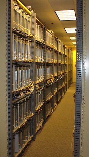
One of the more interesting efforts in this field is John Koza's invention machine, which applies GAs to a very wide variety of design problems, and which has produced a number of new patents for designs that did not originate in human imaginations.


NASA used genetic algorithms to design microwave antennas for the ST5 mission to measure the Earth's magnetosphere. There is some discussion of this work on Wikipedia.

While genetic algorithms are the most widely known of this class of algorithms, simulated annealing has a decades-long history of success in the placing and routing of FPGAs and custom integrated circuits. Other applications for global optimization include scheduling and resource allocation.

Random links

Monday, July 24, 2006

Spimes

Bruce Sterling gave an interesting talk at a SIGGRAPH conference in 2004. He described two kinds of human artifacts, blobjects and spimes. Blobjects are simply artifacts that have been designed with modern CAD systems, so their shapes are more curvy and sexy than the same-functioned artifacts of past generations. Examples are the iMac and the new VW beetle.

The spime is a different beast. It is jam-packed full of information technology. It has RFID or Bluetooth to talk to nearby computers (or maybe other spimes). It has GPS so it knows where on Earth it is. It knows how to connect to the Internet. It willingly participates in data mining efforts by Google and other search engines and advertisers. In addition to being designed with a CAD system, it might be manufactured with rapid prototyping techniques such as 3D printers.

Sterling's predictions about the spimes' use of information are cynical. They are programmed by the corporations that built them. They collect consumer demographics information about the people who buy and use them. Their first allegiance is to their manufacturer. They are smart enough that the distinction has teeth - the hand drill I bought at Sears does not change its behavior to act in Sears' best interests rather than mine.

If spimes aren't nanotechnology, why am I writing about them in a nanotech blog? Because they shake loose my thinking about what products could be. I hadn't thought about ANY of this stuff before I read the transcript of Sterling's talk. My cell phone today has way more computing power than the Apollo guidance computer had. When a ballpoint pen has way more computing power than my cell phone has today, of course somebody will program it to do things like this.

Wednesday, July 12, 2006

More hoverboard progress

I made the skirt tighter, and I improved the air seal between the leafblower and the skirt feed. For a couple of reasons, I can't successfully ride on the thing myself.
  • The plywood base isn't wide enough, so it's very hard to balance.
  • The plywood base isn't stiff enough, so it flexes under my weight.
  • The air connections need to be better, the duct tape keeps leaking.
  • It's probably a good idea to strap the leafblower engine down to the plywood permanently - leafblowers are cheap nowadays.
Here is what it can do. With the leafblower engine idling, it can hover its own weight quite nicely, and then I can kick it around a parking lot like a hockey puck sliding over ice. Here's a video of that happening.

To a zeroth-order approximation, there are two kinds of engineering styles, planning and prototyping. A planner tries to think through every possible detail or failure mode first, plans out everything on paper, and only then does he pick up his tools and start building. A prototyper begins with a general idea of his goal, grabs his roll of duct tape, and starts putting together the cheapest, cheesiest possible version that will work. With prototyping I discover principles and failure modes that I might never have found by thinking ahead. Besides, I get to take cool videos sooner than later.

When I was a young child, I was by necessity a planner because I didn't have any stuff to build with. So I'd think about things and imagine things and try to reason through as many implications and ramifications as I could. The balance between planning and prototyping is economical. The cost of prototyping is materials, labor, and the risk of problems that might have been avoided with planning. The cost of planning is time, and the risk of problems that can't be foreseen until you have a working model. Simulation is a half-way approach - a good simulator will alert you to problems you didn't foresee with pure analysis and design, but is cheaper than building a prototype.

But you can't shoot the video until you have the prototype. And the video is very cool.

Saturday, July 08, 2006

Building a hoverboard

I'm going to try to build a hoverboard. Here are some videos of people building and playing with hoverboards:
  • One
  • Two
  • Long and detailed with info about design principles
  • Here is a TV show in England where a guy built one and provided lots of instructions.
These all run with gasoline-powered leafblowers. Some of them are designed so that the leafblower doesn't need to be destroyed. I have a leafblower, so here we go. The clearest instructions I could find for doing this were here. I found some 1/4-inch plywood in the garage and cut out an oval-shaped board on the table saw. I cut out some thick plastic blue tarp for the skirt. All this stuff came from Home Depot. Here's the leafblower, with its elliptical snout. I will need an elliptical hole in the board to put the snout in, so the underside of the board can fill with air. Here are the tools for making the elliptical snout hole. It came out a little rough, but I hope to put something soft or foamy around it anyway, to help seal it, so I think I can tolerate this much slop. There is also a hole in the center, for a bolt that will hold the middle of the curtain to the top of the board. So I got the thing put together. I connected the center of the skirt to the bottom of the board with a plywood disc strain relief. I stapled the skirt to the top of the board and duct-taped liberally all the way around the edge of the skirt. I put some duct tape around the elliptical snout hole to help the seal. I don't think the duct tape around the snout hole did much good, the gap was still quite big. I may decide to sacrifice the leafblower after all, or maybe its normal snout is removable and replaceable with a hose whose other end could be liberally duct-taped to the board. I got the thing working, after a fashion. I climbed aboard, trying standing, sitting, and kneeling positions. I had made the skirt too baggy, so the craft was much too tippy. Trying to just keep it balanced had me sweating like a horse. A couple of times, I was able to balance it well enough that it started to move frictionlessly for a second or two. Then I uploaded my FIRST GOOGLE VIDEO EVER!!! OMG PONIES!!!! I need a tighter skirt, and a better seal for the leafblower. I might want to see about finding a lighter passenger. References